Centrifugal Concentrator
ProductOverview
A centrifugal gold concentrator is a spinning conical bowl that exploits centrifugal force to achieve gravity concentration of fine gold particles. Fine gold (−100 μm, particularly −50 μm and finer) is poorly recovered by conventional gravity devices like shaking tables or spirals because viscous drag and Brownian motion dominate over gravitational force at small particle sizes. The centrifugal concentrator overcomes this by applying artificial gravity (100–300 G), dramatically increasing the effective weight and settling velocity of fine gold particles.
The principle is similar to a panning operation, but mechanized and continuous. A rotating conical bowl is fed with fine ore slurry; centrifugal force drives heavy particles (gold) toward the bowl wall, where they are trapped by internal riffles and concentrated. The system is primarily used in final-stage gold recovery, processing mill tailings, sulfide concentrates, or refractory ore leach solutions. Small units (1–3 kW) are ideal for artisanal operations; medium units (5–10 kW) suit small mines processing 5–50 t/day.
How it works
Prepared ore slurry (fine, well-sized particles, 30–50% solids) is fed tangentially into the rotating spinning bowl via a feed pump at a controlled rate. The bowl rotates at 600–1200 rpm, generating centrifugal acceleration of 100–300 G at the bowl wall (G-force is roughly proportional to rpm² and bowl diameter).
Inside the spinning bowl, particles experience:
- Centrifugal force: Radially outward, proportional to particle mass, rotation speed, and radius.
- Friction drag: From the slurry medium, opposing radial motion.
- Gravity: Downward (vertical).
For a fine gold particle (ρ = 19.3 g/cm³) in the high-acceleration field:
- Centrifugal force dominates, pushing the particle toward the bowl wall (outer radius).
- Light gangue (e.g., quartz, ρ = 2.6 g/cm³) experiences far less centrifugal force; it remains suspended in the slurry and is swept toward the outlet.
The bowl's interior is ribbed with spiral riffles that trap and guide heavy particles downward and inward toward the bowl apex. Once concentrated at the bottom, heavy particles settle into a "heavy mineral bed" and are periodically extracted via a discharge valve.
To prevent particle blinding (where the concentrate bed becomes too dense and stops accepting new particles), the fluidization system continuously injects water upward through the bowl base at a controlled pressure (20–100 kPa). This maintains a semi-fluidized state: the concentrate bed is loose and porous, allowing new heavy particles to percolate down through it, while light particles and water escape toward the discharge.
Bowl Design and Acceleration
The conical bowl is typically stainless steel (316SS to resist corrosion from slurry salts and acidic solutions). The cone angle is usually 40–60° from vertical; this geometry maximizes particle settlement area while minimizing dead zones.
The bowl's internal riffles are helical or spiral channels, milled into the cone surface or bolted on as inserts. They serve two purposes:
- Particle guidance: Riffles naturally channel settling particles toward the center axis.
- Separation: Riffles create local low-velocity zones where very fine particles can settle without being swept away.
Centrifugal acceleration (G-force) at the bowl wall is: G = ω² r / g = (2π n / 60)² r / g
Where:
- n = rpm
- r = bowl radius
- g = gravitational acceleration (9.81 m/s²)
For a typical 0.5 m diameter bowl at 1000 rpm: G ≈ (2π × 1000 / 60)² × 0.25 / 9.81 ≈ 275 G
This 275× magnification of gravity allows −50 μm gold particles to settle in minutes, whereas they would require hours or days in a regular gravity device.
Fluidization Control
The fluidization system is essential for sustained operation. Water pressure at the bowl base is maintained at 20–100 kPa (user-adjustable) via a proportional valve. Higher fluidization pressure loosens the concentrate bed but risks sweeping fine gold particles out with the overflow. Lower pressure allows finer particles to settle but risks "seizing" the bed.
The PLC continuously monitors fluidization pressure and adjusts the valve to maintain optimal conditions. This is one reason modern centrifugal concentrators are more effective than older designs: automated fluidization feedback allows sub-microgram gold particles to be recovered without operator skill.
Discharge and Concentrate Recovery
Every 30–120 minutes (user-programmable), the discharge valve at the bowl apex opens, and accumulated heavy concentrate is expelled by gravity or with the aid of a small extraction pump. The concentrate is collected in a chute for weighing, assaying, and further processing (fine gravity panning, fire assay, etc.).
Concentrate volume is typically small (0.5–2 liters per discharge cycle), but extremely rich in gold. A unit processing 5 t/day of gold mill tailings (typically 0.5–2 g/t gold) may produce 20–50 g of concentrate per discharge, a sharp enrichment from 1 ppm to 100,000+ ppm.
Optimization and Tuning
Three parameters affect recovery and grade:
Bowl speed: Increasing rpm from 600 to 1200 rpm increases G-force by 4× (since G ∝ rpm²), improving recovery of ultra-fine gold but increasing power consumption. Most operators run at 800–1000 rpm as a compromise.
Fluidization pressure: Higher pressure (80–100 kPa) keeps the bed loose, maximizing new particle entry. Lower pressure (20–40 kPa) concentrates a heavier bed, improving grade but risking particle loss. Optimal pressure is found empirically.
Feed rate: Higher throughput increases capacity but reduces residence time, worsening recovery of fine particles. Lower feed rates improve recovery but are uneconomic. Typical setpoint is 2–5 t/h per unit.
Feed particle size is critical: material coarser than −500 μm is poorly recovered; material finer than −5 μm is optimal. Pre-screening or hydrocyclone classification upstream is often justified.
Applications and Variations
Primary application: Gold tailings retreatment
- Small mines and artisanal operations reprocess old tailings dams using centrifugal concentrators.
- Recovers previously lost fine gold, increasing project economic life.
Sulfide concentrate processing
- High-grade gold-copper concentrates are fed to a centrifugal concentrator to pre-concentrate before flotation or smelting.
Refractory ore leaching
- Leach solutions containing dissolved gold are clarified (solids removed) via centrifugal concentrator before gold precipitation.
Variations:
- Bowl size: Units range from 0.3 m (1–3 kW, 1 t/h) to 1.0 m (10 kW, 10 t/h).
- Speed: Industrial models operate 600–2000 rpm; higher speeds increase G-force but add mechanical stress.
- Automation: Older models require manual feed rate and fluidization adjustment; modern units employ PLC with touchscreen, automatic discharge, and data logging.
Comparison to Other Gravity Methods
| Method | Recovery at −50 μm | Capacity (t/h) | Capital Cost | Operator Skill |
|---|---|---|---|---|
| Shaking Table | 70–85% | 2–10 | $5k–30k | High |
| Spiral Concentrator | 75–90% | 5–50 | $20k–50k | Medium |
| Dense Media Separator | 80–95% (−100 μm) | 50–500 | $100k–300k | Low |
| Centrifugal Concentrator | 85–98% | 1–10 | $30k–100k | Low |
The centrifugal concentrator excels at recovery of ultra-fine gold but processes lower tonnages than other methods.
Maintenance and Durability
The main bearing supporting the spinning bowl is subject to high centrifugal loads; it should be inspected quarterly and replaced every 2–3 years. Stainless steel bowl erosion is slow; with normal operation, the bowl lasts 5–10 years. The variable frequency drive is the most failure-prone component; drives should be protected from moisture and dust, with annual filter cleaning.
Modern units include automatic PLC control with data logging, allowing remote monitoring and predictive maintenance scheduling.
Advantages and Challenges
Advantages:
- Highest recovery of fine gold (−50 μm) among gravity concentrators.
- Compact footprint (1 m² floor space).
- Low power consumption (1–10 kW).
- Suited to wet processing and acidic solutions (unlike some gravity devices).
- Automatic operation reduces operator dependence.
Challenges:
- High capital cost per unit ($30k–$100k) for small throughputs.
- Sensitive to feed size distribution; requires pre-screening.
- Concentrate grade (30–70%) often requires follow-up treatment.
- Vibration can be problematic; proper foundation and isolation are essential.
- Stainless steel bowl is expensive to repair or replace.
Small-scale gold miners and processors increasingly adopt centrifugal concentrators for final-stage gold recovery, often in combination with a shaking table (primary concentrate) + centrifugal concentrator (fine tailings recovery) circuit.
Centrifugal Concentrator parts and their functions
8 top-level parts · 24 parts in total · full bill of materials below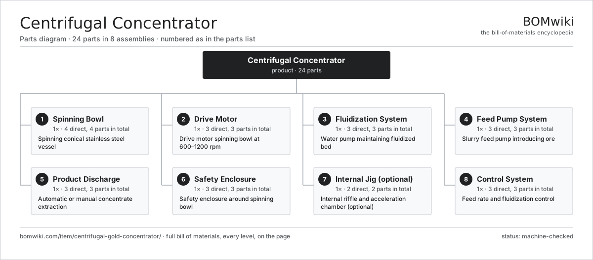
| # | Part | Qty | What it does |
|---|---|---|---|
| 1 | Spinning Bowl 4 parts | 1× | Spinning conical stainless steel vessel |
| 2 | Drive Motor 3 parts | 1× | Drive motor spinning bowl at 600–1200 rpm |
| 3 | Fluidization System 3 parts | 1× | Water pump maintaining fluidized bed |
| 4 | Feed Pump System 3 parts | 1× | Slurry feed pump introducing ore |
| 5 | Product Discharge 3 parts | 1× | Automatic or manual concentrate extraction |
| 6 | Safety Enclosure 3 parts | 1× | Safety enclosure around spinning bowl |
| 7 | Internal Jig (optional) 2 parts | 1× | Internal riffle and acceleration chamber (optional) |
| 8 | Control System 3 parts | 1× | Feed rate and fluidization control |
3D model
No 3D model yet. Have a CAD file of this? Add a 3D model — STL renders right on this page; STEP, FreeCAD, and OpenSCAD sources are welcome too (openly licensed, like all 3D models on BOMwiki).
Build & assembly graph
expand / collapse · shared sub-assemblies converge · links to related products · est. labourTap an assembly to expand/collapse · tap a part to open it · use “Open page” for any node · drag to pan, scroll to zoom.
Bill of materials for Centrifugal Concentrator
8 top-level lines · 32 rows shown · 24 parts total · indented to 3 levels| # | Item / sub-assembly | Part no. | Qty/assy | Ext. qty | Parts | Type |
|---|---|---|---|---|---|---|
| 1 | Spinning Bowl 4 parts | centrifugal-gold-concentrator-bowl | 1× | 1 | 4 | assembly |
| 1.1 | Cone Body | centrifugal-gold-concentrator-cone-body | 1× | 1 | · | part |
| 1.2 | Internal Riffles | centrifugal-gold-concentrator-internal-riffles | 1× | 1 | · | part |
| 1.3 | Main Bearing | centrifugal-gold-concentrator-bearing-journal | 1× | 1 | · | part |
| 1.4 | Bowl Shaft | centrifugal-gold-concentrator-shaft | 1× | 1 | · | part |
| 2 | Drive Motor 3 parts | centrifugal-gold-concentrator-drive-motor | 1× | 1 | 3 | assembly |
| 2.1 | AC Induction Motor | centrifugal-gold-concentrator-motor | 1× | 1 | · | part |
| 2.2 | Variable Frequency Drive | centrifugal-gold-concentrator-vfd | 1× | 1 | · | part |
| 2.3 | Motor Coupling | centrifugal-gold-concentrator-motor-coupling | 1× | 1 | · | part |
| 3 | Fluidization System 3 parts | centrifugal-gold-concentrator-fluidization-system | 1× | 1 | 3 | assembly |
| 3.1 | Fluidization Pump | centrifugal-gold-concentrator-fluidization-pump | 1× | 1 | · | part |
| 3.2 | Fluidization Manifold | centrifugal-gold-concentrator-fluidization-manifold | 1× | 1 | · | part |
| 3.3 | Fluidization Valve | centrifugal-gold-concentrator-fluidization-control | 1× | 1 | · | part |
| 4 | Feed Pump System 3 parts | centrifugal-gold-concentrator-feed-pump | 1× | 1 | 3 | assembly |
| 4.1 | Feed Slurry Pump | centrifugal-gold-concentrator-feed-pump-unit | 1× | 1 | · | part |
| 4.2 | Feed Pump Motor | centrifugal-gold-concentrator-feed-motor | 1× | 1 | · | part |
| 4.3 | Feed Inlet | centrifugal-gold-concentrator-feed-manifold | 1× | 1 | · | part |
| 5 | Product Discharge 3 parts | centrifugal-gold-concentrator-product-discharge | 1× | 1 | 3 | assembly |
| 5.1 | Discharge Valve | centrifugal-gold-concentrator-discharge-valve | 1× | 1 | · | part |
| 5.2 | Concentrate Chute | centrifugal-gold-concentrator-concentrate-chute | 1× | 1 | · | part |
| 5.3 | Concentrate Discharge Pump | centrifugal-gold-concentrator-discharge-pump | 1× | 1 | · | part |
| 6 | Safety Enclosure 3 parts | centrifugal-gold-concentrator-housing | 1× | 1 | 3 | assembly |
| 6.1 | Guard Panels | centrifugal-gold-concentrator-guard-panels | 1× | 1 | · | part |
| 6.2 | Drain Tray | centrifugal-gold-concentrator-drain-tray | 1× | 1 | · | part |
| 6.3 | Splash Guard | centrifugal-gold-concentrator-splash-deflector | 1× | 1 | · | part |
| 7 | Internal Jig (optional) 2 parts | centrifugal-gold-concentrator-mineral-jig | 1× | 1 | 2 | assembly |
| 7.1 | Jig Riffle Assembly | centrifugal-gold-concentrator-jig-riffle | 1× | 1 | · | part |
| 7.2 | Jig Support | centrifugal-gold-concentrator-jig-support | 1× | 1 | · | part |
| 8 | Control System 3 parts | centrifugal-gold-concentrator-control-system | 1× | 1 | 3 | assembly |
| 8.1 | Feed Flow Meter | centrifugal-gold-concentrator-feed-flowmeter | 1× | 1 | · | part |
| 8.2 | Pressure Transducer | centrifugal-gold-concentrator-pressure-transducer | 1× | 1 | · | part |
| 8.3 | Centrifuge Controller | centrifugal-gold-concentrator-plc | 1× | 1 | · | part |
Sourcing: possible vendors
Prices, MOQ, and lead times are algorithmic estimates, not quotes, and not claims about these companies. Company mappings are curated by keyword; est. price band $200k–$5M. How estimates work| Vendor | HQ | Specialty | MOQ | Lead time |
|---|---|---|---|---|
| caterpillar.com ↗ | Irving, US | Construction & mining equipment | made to order | 20–36 wks |
|
🇯🇵Komatsu
komatsu.com ↗
|
Tokyo, JP | Construction & mining equipment | made to order | 20–36 wks |
|
🇸🇪Sandvik
rocktechnology.sandvik ↗
|
Stockholm, SE | Mining & rock technology | made to order | 20–36 wks |
|
🇸🇪Epiroc
epiroc.com ↗
|
Stockholm, SE | Mining & drilling equipment | made to order | 20–36 wks |
|
🇫🇮Metso
metso.com ↗
|
Helsinki, FI | Crushing & minerals processing | made to order | 20–36 wks |
1,408-word article