Desiccant Air Dryer
ProductOverview
A desiccant air dryer removes water vapor from compressed air down to −40 °C dew point or lower, essential for spray painting, precision instrument supplies, and any process sensitive to moisture. Unlike refrigerant dryers (which cool air to condense water), desiccant dryers use a water-absorbing solid, typically silica gel or molecular sieve, to bind moisture molecules. The twin-tower design alternates between a wet tower (absorbing moisture) and a dry tower (being hot-regenerated), allowing continuous operation without system shutdown.
How it works
Moist compressed air enters through the Inlet Filter, which removes particles that would clog the desiccant. Air then flows downward through one Desiccant Tower, say the wet tower. The Desiccant Load, granules of silica gel or zeolite, absorbs water molecules from the air; the dry air exits at the outlet.
Meanwhile, the second (dry) tower is in regeneration mode. The Heater Element warms it to 80–90 °C, and the Purge System flows a fraction (10–20%) of the dried main air backwards through the hot tower. This heated purge air evaporates the absorbed water, carrying it to the exhaust silencer. Once regeneration is complete, the Switching Valve, a four-way solenoid valve, reverses the flow: the regenerated tower becomes the active dryer, and the wet tower begins its regeneration cycle.
The Dryer Controller orchestrates this cycle via a simple timer (4–8 hours typical) or, in advanced units, responds to a Dew Point Sensor that measures actual outlet dew point and triggers early switchover if the outlet is already very dry. A Color Indicator Card card in each tower shows saturation state (blue = dry, pink = wet); technicians inspect these to know when to replace the Desiccant Load.
Regeneration and maintenance
The Inlet Filter cartridge requires regular inspection and replacement (typically every 1000 operating hours or when differential pressure exceeds 2.5 bar). The desiccant granules, whether silica gel or molecular sieve, regenerate thermally but eventually fail to re-dry completely. Full replacement occurs every 2–5 years depending on inlet air quality and duty cycle.
If the outlet dew point rises above specification, check that the heater is reaching temperature (verify with a temperature gauge on the regenerating tower), that the purge regulator is not stuck, and that inlet moisture load has not drastically increased. A clogged inlet filter can restrict purge flow and compromise regeneration.
Sizing and efficiency
Desiccant dryers consume 10–20% of their throughput air as regeneration purge, making them less energy-efficient than refrigerant dryers at high flow rates. However, they excel in extreme conditions: sub-zero ambient temperatures (where refrigerant units freeze), very low dew-point requirements (−60 °C or lower), and dusty environments where water accumulation risk is high. Many large plants use refrigerant pre-dryers to remove the bulk of moisture, then desiccant towers as a polishing stage for compressed-gas standard compliance.
Desiccant Air Dryer parts and their functions
8 top-level parts · 43 parts in total · full bill of materials below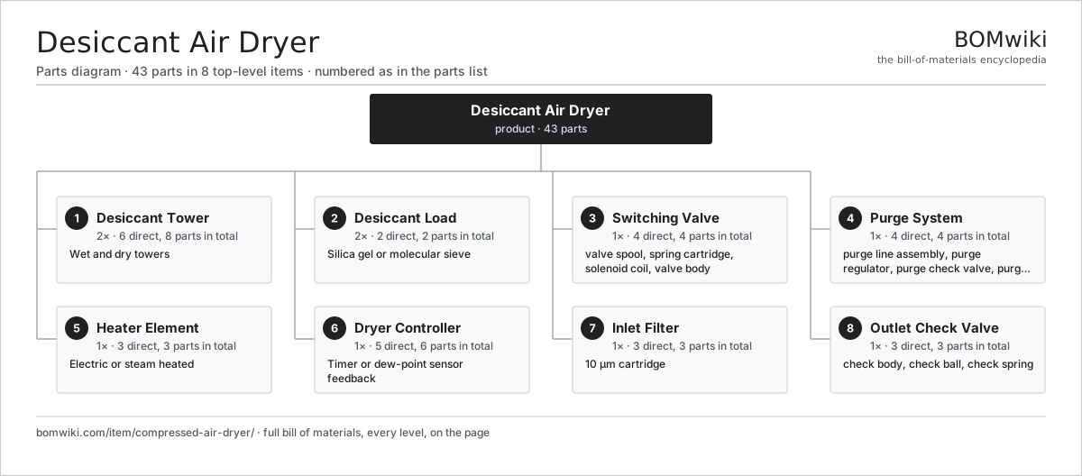
| # | Part | Qty | What it does |
|---|---|---|---|
| 1 | Desiccant Tower 6 parts | 2× | Wet and dry towers |
| 2 | Desiccant Load 2 parts | 2× | Silica gel or molecular sieve |
| 3 | Switching Valve 4 parts | 1× | Four-way solenoid or pneumatic pilot valve that directs air flow between towers. |
| 4 | Purge System 4 parts | 1× | Directs a fraction of dried air back through the saturated tower during regeneration to drive off moisture. |
| 5 | Heater Element 3 parts | 1× | Electric or steam heated |
| 6 | Dryer Controller 5 parts | 1× | Timer or dew-point sensor feedback |
| 7 | Inlet Filter 3 parts | 1× | 10 μm cartridge |
| 8 | Outlet Check Valve 3 parts | 1× | Prevents backflow during tower switch-over. |
3D model
No 3D model yet. Have a CAD file of this? Add a 3D model. STL renders right on this page; STEP, FreeCAD, and OpenSCAD sources are welcome too (openly licensed, like all 3D models on BOMwiki).
Build & assembly graph
expand / collapse · shared sub-assemblies converge · links to related products · est. labourTap an assembly to expand/collapse · tap a part to open it · use “Open page” for any node · drag to pan, scroll to zoom.
Bill of materials for Desiccant Air Dryer
8 top-level lines · 40 rows shown · 43 parts total · indented to 3 levels| # | Item / sub-assembly | Part no. | Qty/assy | Ext. qty | Parts | Type |
|---|---|---|---|---|---|---|
| 1 | Desiccant Tower 6 parts | compressed-air-dryer-tower-assembly | 2× | 2 | 8 | assembly |
| 1.1 | Tower Shell | compressed-air-dryer-tower-shell | 1× | 2 | · | part |
| 1.2 | Tower Header | compressed-air-dryer-tower-header | 1× | 2 | · | part |
| 1.3 | Tower Base | compressed-air-dryer-tower-base | 1× | 2 | · | part |
| 1.4 | Desiccant Load 2 parts | compressed-air-dryer-desiccant-load | 1× | 2 | 2 | assembly |
| 1.4.1 | Desiccant Granules | compressed-air-dryer-desiccant-granule | 1× | 2 | · | part |
| 1.4.2 | Color Indicator Card | compressed-air-dryer-color-indicator | 1× | 2 | · | part |
| 1.5 | Desiccant Screen | compressed-air-dryer-desiccant-screen | 2× | 4 | · | part |
| 1.6 | Tower Seal Ring | compressed-air-dryer-tower-seal | 1× | 2 | · | part |
| 2 | Desiccant Load 2 parts | compressed-air-dryer-desiccant-load | 2× | 2 | 2 | assembly |
| 2.1 | Desiccant Granules | compressed-air-dryer-desiccant-granule | 1× | 2 | · | part |
| 2.2 | Color Indicator Card | compressed-air-dryer-color-indicator | 1× | 2 | · | part |
| 3 | Switching Valve 4 parts | compressed-air-dryer-switching-valve | 1× | 1 | 4 | assembly |
| 3.1 | Valve Spool | compressed-air-dryer-spool | 1× | 1 | · | part |
| 3.2 | Spring Cartridge | compressed-air-dryer-spool-spring | 1× | 1 | · | part |
| 3.3 | Solenoid Coil | compressed-air-dryer-solenoid-coil | 1× | 1 | · | part |
| 3.4 | Valve Body | compressed-air-dryer-valve-body | 1× | 1 | · | part |
| 4 | Purge System 4 parts | compressed-air-dryer-purge-system | 1× | 1 | 4 | assembly |
| 4.1 | Purge Line Assembly | compressed-air-dryer-purge-line | 1× | 1 | · | part |
| 4.2 | Purge Regulator | compressed-air-dryer-purge-regulator | 1× | 1 | · | part |
| 4.3 | Purge Check Valve | compressed-air-dryer-purge-check | 1× | 1 | · | part |
| 4.4 | Purge Silencer | compressed-air-dryer-silencer | 1× | 1 | · | part |
| 5 | Heater Element 3 parts | compressed-air-dryer-heater-element | 1× | 1 | 3 | assembly |
| 5.1 | Heating Element | heating-element | 1× | 1 | · | part |
| 5.2 | Thermostat | compressed-air-dryer-heater-thermostat | 1× | 1 | · | part |
| 5.3 | Safety Cutoff Switch | compressed-air-dryer-heater-safety | 1× | 1 | · | part |
| 6 | Dryer Controller 5 parts | compressed-air-dryer-controller | 1× | 1 | 6 | assembly |
| 6.1 | Timer Board | compressed-air-dryer-timer-board | 1× | 1 | · | part |
| 6.2 | Dew Point Sensor | compressed-air-dryer-dew-sensor | 1× | 1 | · | part |
| 6.3 | Solenoid Driver | compressed-air-dryer-solenoid-driver | 1× | 1 | · | part |
| 6.4 | Microcontroller | mcu | 1× | 1 | · | part |
| 6.5 | Relay | relay | 2× | 2 | · | part |
| 7 | Inlet Filter 3 parts | compressed-air-dryer-inlet-filter | 1× | 1 | 3 | assembly |
| 7.1 | Inlet Bowl | compressed-air-dryer-inlet-bowl | 1× | 1 | · | part |
| 7.2 | Inlet Cartridge | compressed-air-dryer-inlet-cartridge | 1× | 1 | · | part |
| 7.3 | Inlet Drain Cock | compressed-air-dryer-inlet-drain | 1× | 1 | · | part |
| 8 | Outlet Check Valve 3 parts | compressed-air-dryer-outlet-check | 1× | 1 | 3 | assembly |
| 8.1 | Check Body | compressed-air-dryer-check-body | 1× | 1 | · | part |
| 8.2 | Check Ball | compressed-air-dryer-check-ball | 1× | 1 | · | part |
| 8.3 | Check Spring | compressed-air-dryer-check-spring | 1× | 1 | · | part |
Something wrong in this list? Report a problem with this BOM.
Related products
same domain, ranked by shared parts Radial Spillway Gate
264 parts · shares 3 with this page
 Air Compressor
97 parts · shares 2 with this page
 Ball Valve
61 parts · shares 2 with this page
 Irrigation Pump Station
1,881 parts · shares 2 with this page
 Rotary Screw Air Compressor
84 parts · shares 2 with this page
 Sluice Gate
123 parts · shares 2 with this page
Sourcing: possible vendors
Browse the supplier directory → Prices, MOQ, and lead times are algorithmic estimates, not quotes, and not claims about these companies. Company mappings are curated by keyword; est. price band $50–$50k. How estimates work| Vendor | HQ | Specialty | MOQ | Lead time |
|---|---|---|---|---|
|
🇩🇰Grundfos
grundfos.com ↗
|
Bjerringbro, DK | Pumps | 200 units | 6–12 wks |
|
🇺🇸Xylem
xylem.com ↗
|
Washington, US | Water technology | 200 units | 6–12 wks |
| flowserve.com ↗ | Irving, US | Pumps & valves | 200 units | 6–12 wks |
|
🇩🇪KSB
ksb.com ↗
|
Frankenthal, DE | Pumps & valves | 200 units | 6–12 wks |
| parker.com ↗ | Cleveland, US | Motion & fluid control | 200 units | 6–12 wks |
506-word article