Condensate Removal Pump
ProductOverview
A condensate pump removes the water that cooling and heating equipment produces when it cannot drain by gravity. An air conditioner's evaporator, a high-efficiency furnace, or a dehumidifier all shed liquid water, and when the appliance sits below or far from a drain that water has to be lifted. The pump collects condensate in a small reservoir and, each time the reservoir fills, switches on briefly to push the water up a thin tube to a sink, standpipe or drain line.
The Reservoir catches the water and carries the float switch. Above it the Drive Motor drives the Pump End, and the Discharge lifts the water out through a check valve. The Inlet & Safety accepts several drain lines and adds a safety cutoff, the Housing encloses it all, and the Power Cord supplies power.
How it works
Condensate drips into the Collection Tank through the Inlet Ports. As the level rises, the Float lifts along its Float Guide until it trips the switch, closing a Relay that starts the motor. The motor spins the Impeller inside the Volute, throwing the water up through the Discharge Tube. The Check Valve holds the lifted column so it does not run back down when the pump stops, and the float drops to shut the pump off after a few seconds of running.
Because a failed condensate pump would let water overflow onto the floor or back up into the equipment, a second Safety Switch sits higher in the reservoir. If the water rises past the normal start level, that switch opens a circuit wired to the HVAC equipment and shuts it down before the tank can spill. The Ball Bearing-supported motor and sealed Housing keep the electrics dry, and the Wire Bundle and Connector land power at the motor from the grounded cord.
Condensate Removal Pump parts and their functions
9 top-level parts · 44 parts in total · full bill of materials below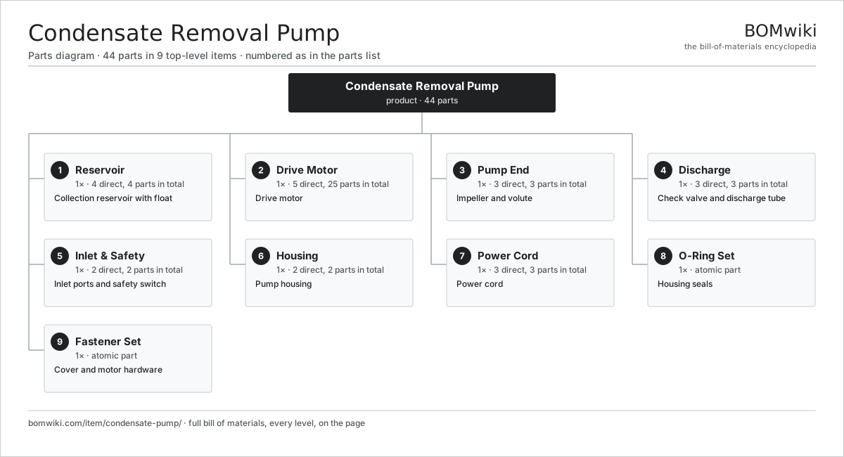
| # | Part | Qty | What it does |
|---|---|---|---|
| 1 | Reservoir 4 parts | 1× | Collection reservoir with float |
| 2 | Drive Motor 5 parts | 1× | Drive motor |
| 3 | Pump End 3 parts | 1× | Impeller and volute |
| 4 | Discharge 3 parts | 1× | Check valve and discharge tube |
| 5 | Inlet & Safety 2 parts | 1× | Inlet ports and safety switch |
| 6 | Housing 2 parts | 1× | Pump housing |
| 7 | Power Cord 3 parts | 1× | Power cord |
| 8 | O-Ring Set | 1× | Housing seals |
| 9 | Fastener Set | 1× | Cover and motor hardware |
3D model
No 3D model yet. Have a CAD file of this? Add a 3D model. STL renders right on this page; STEP, FreeCAD, and OpenSCAD sources are welcome too (openly licensed, like all 3D models on BOMwiki).
Build & assembly graph
expand / collapse · shared sub-assemblies converge · links to related products · est. labourTap an assembly to expand/collapse · tap a part to open it · use “Open page” for any node · drag to pan, scroll to zoom.
Bill of materials for Condensate Removal Pump
9 top-level lines · 38 rows shown · 44 parts total · indented to 3 levels| # | Item / sub-assembly | Part no. | Qty/assy | Ext. qty | Parts | Type |
|---|---|---|---|---|---|---|
| 1 | Reservoir 4 parts | condensate-pump-reservoir | 1× | 1 | 4 | assembly |
| 1.1 | Collection Tank | condensate-pump-tank | 1× | 1 | · | part |
| 1.2 | Float | condensate-pump-float | 1× | 1 | · | part |
| 1.3 | Relay | relay | 1× | 1 | · | part |
| 1.4 | Float Guide | condensate-pump-float-guide | 1× | 1 | · | part |
| 2 | Drive Motor 5 parts | condensate-pump-motor | 1× | 1 | 25 | assembly |
| 2.1 | Stator Assembly 3 parts | stator-assembly | 1× | 1 | 3 | assembly |
| 2.1.1 | Stator Core (laminations) | stator-core | 1× | 1 | · | part |
| 2.1.2 | Copper Winding | copper-winding | 1× | 1 | · | part |
| 2.1.3 | Slot Insulation | stator-insulation | 1× | 1 | · | part |
| 2.2 | Rotor Assembly 4 parts | rotor-assembly | 1× | 1 | 19 | assembly |
| 2.2.1 | Rotor Shaft | rotor-shaft | 1× | 1 | · | part |
| 2.2.2 | Rotor Core | rotor-core | 1× | 1 | · | part |
| 2.2.3 | Neodymium Magnet | neodymium-magnet | 16× | 16 | · | part |
| 2.2.4 | Ball Bearing | ball-bearing | 1× | 1 | · | part |
| 2.3 | Copper Winding | copper-winding | 1× | 1 | · | part |
| 2.4 | Motor Housing | motor-housing | 1× | 1 | · | part |
| 2.5 | Ball Bearing | ball-bearing | 1× | 1 | · | part |
| 3 | Pump End 3 parts | condensate-pump-pump-end | 1× | 1 | 3 | assembly |
| 3.1 | Impeller | condensate-pump-impeller | 1× | 1 | · | part |
| 3.2 | Volute | condensate-pump-volute | 1× | 1 | · | part |
| 3.3 | O-Ring Set | oring-set | 1× | 1 | · | part |
| 4 | Discharge 3 parts | condensate-pump-discharge | 1× | 1 | 3 | assembly |
| 4.1 | Check Valve | condensate-pump-check-valve | 1× | 1 | · | part |
| 4.2 | Discharge Tube | condensate-pump-tube | 1× | 1 | · | part |
| 4.3 | Barb Fitting | condensate-pump-barb | 1× | 1 | · | part |
| 5 | Inlet & Safety 2 parts | condensate-pump-inlet | 1× | 1 | 2 | assembly |
| 5.1 | Inlet Ports | condensate-pump-inlet-ports | 1× | 1 | · | part |
| 5.2 | Safety Switch | condensate-pump-safety-switch | 1× | 1 | · | part |
| 6 | Housing 2 parts | condensate-pump-housing | 1× | 1 | 2 | assembly |
| 6.1 | Cover | condensate-pump-cover | 1× | 1 | · | part |
| 6.2 | O-Ring Set | oring-set | 1× | 1 | · | part |
| 7 | Power Cord 3 parts | condensate-pump-cord | 1× | 1 | 3 | assembly |
| 7.1 | Wire Bundle | wire-bundle | 1× | 1 | · | part |
| 7.2 | Connector | connector | 1× | 1 | · | part |
| 7.3 | Power Plug | condensate-pump-plug | 1× | 1 | · | part |
| 8 | O-Ring Set | oring-set | 1× | 1 | · | part |
| 9 | Fastener Set | fastener-set | 1× | 1 | · | part |
Something wrong in this list? Report a problem with this BOM.
Related products
same domain, ranked by shared parts Heat-Pump Water Heater
152 parts · shares 14 with this page
Hot Water Recirculation Pump
107 parts · shares 14 with this page
Sewage/Effluent Pump
47 parts · shares 14 with this page
 HDPE Pipe Butt-Fusion Machine
110 parts · shares 13 with this page
Pipe Threading Machine
79 parts · shares 13 with this page
 Macerating Toilet
62 parts · shares 13 with this page
Sourcing: possible vendors
Browse the supplier directory → Prices, MOQ, and lead times are algorithmic estimates, not quotes, and not claims about these companies. Company mappings are curated by keyword; est. price band $20–$3k. How estimates work| Vendor | HQ | Specialty | MOQ | Lead time |
|---|---|---|---|---|
|
🇺🇸Kohler
kohler.com ↗
|
Kohler, US | Plumbing fixtures | 1,000 units | 6–12 wks |
|
🇯🇵TOTO
toto.com ↗
|
Kitakyushu, JP | Sanitaryware | 1,000 units | 6–12 wks |
|
🇯🇵LIXIL
lixil.com ↗
|
Tokyo, JP | Plumbing (Grohe, American Std) | 1,000 units | 6–12 wks |
|
🇺🇸Moen
moen.com ↗
|
North Olmsted, US | Faucets & fixtures | 1,000 units | 6–12 wks |
|
🇨🇭Geberit
geberit.com ↗
|
Rapperswil, CH | Sanitary systems | 1,000 units | 6–12 wks |
333-word article