Drum Pump
ProductOverview
A drum pump (barrel pump) empties 200-litre drums, IBCs, and carboys from the top bung opening, replacing the dangerous practice of tipping a quarter-tonne drum to pour from it. The machine is two separable pieces: a hand-held Motor Head and a long Immersion Tube that reaches the drum bottom. One motor can drive a rack of different tubes, polypropylene for acids and alkalis, PVDF for concentrated oxidisers, stainless steel for solvents and flammables, so a single drive serves an entire chemical store. Typical performance is up to 200 L/min and 20 m head, enough to empty a drum in about ninety seconds.
How it works
The Motor Head contains a series-wound universal motor: a wound Rotor Assembly running inside the Stator Assembly field at up to 10,000 rpm, fed through a pair of Carbon Brush contacts and cooled by a shaft-mounted Cooling Fan. The armature rides on two Ball Bearing sets inside the splash-protected Motor Housing Shell. High speed is the point: it lets a very small impeller make useful head, which keeps the whole wetted end slim enough to pass a 2-inch bung.
Torque passes through the Quick-Release Coupling, where a knurled Coupling Hand Nut clamps the tube and a Drive Dog engages the Shaft Socket on the tube's inner shaft, no tools, a few seconds to swap tubes. Inside the Outer Tube, the Inner Shaft runs the full tube length, steadied every few hundred millimetres by a PTFE Shaft Bushing. At the foot, the Impeller, an open axial rotor about 38 mm across, sits in the Suction Foot behind a slotted Foot Strainer. It throws liquid up the annulus between shaft and tube to the Discharge Spout, through the Discharge Hose, and out the trigger-operated Hand Nozzle.
Sealless tubes are standard for most chemicals: the liquid simply drains back when the pump stops. Where vapours are aggressive or the liquid must not contact the upper shaft, a Tube Shaft Seal makes the tube gas-tight.
Mounting and control
The pump hangs in the drum on the Drum Adapter. Its polypropylene Bung Adapter threads into the standard 2-inch buttress bung, the Adapter Seal limits vapour escape, and the sliding Depth Collar sets how close the Suction Foot rides to the drum bottom, close enough to strip the drum nearly dry, leaving residues of under 100 mL with an angled foot.
Electrically, the head carries a 5 m oil-resistant Power Cord, a splash-protected Rocker Switch with low-voltage release (the pump cannot restart by itself after a power cut, a requirement for unattended safety), and a triac Speed Control Board that phase-angle-modulates the universal motor for stepless flow control. A Thermal Fuse in the windings protects against stall and blocked-rotor overheating.
Variants
The centrifugal-impeller tube described here handles thin liquids to roughly 1,000 mPa·s. For honey, resins, and greases up to 100,000 mPa·s, the same motor heads drive progressive-cavity tube ends with a helical rotor in an elastomer stator. Air-motor versions replace the electric head where compressed air is the preferred utility, and ATEX-certified sets with conductive tubes, earthing cables, and gas-tight seals are mandatory for flammables: a stainless tube, an explosion-proof motor, and bonding clamps between pump, drum, and receiving vessel prevent static ignition during solvent transfer.
Selection
Tube material is chosen against a chemical resistance table for the exact concentration and temperature: polypropylene covers most acids and alkalis to 50 °C, PVDF extends to concentrated nitric and chromic acid at 100 °C, stainless 316 covers solvents, and Hastelloy C handles the worst oxidising chlorides. Tube length matches the container, 1,000 mm for a standard 200 L drum, 1,200 mm for IBCs. Sizing errors show up fast at 10,000 rpm, so manufacturers publish viscosity and density derating curves; running a thin-liquid impeller in 5,000 mPa·s product simply stalls the flow while the motor overheats.
Drum Pump parts and their functions
7 top-level parts · 58 parts in total · full bill of materials below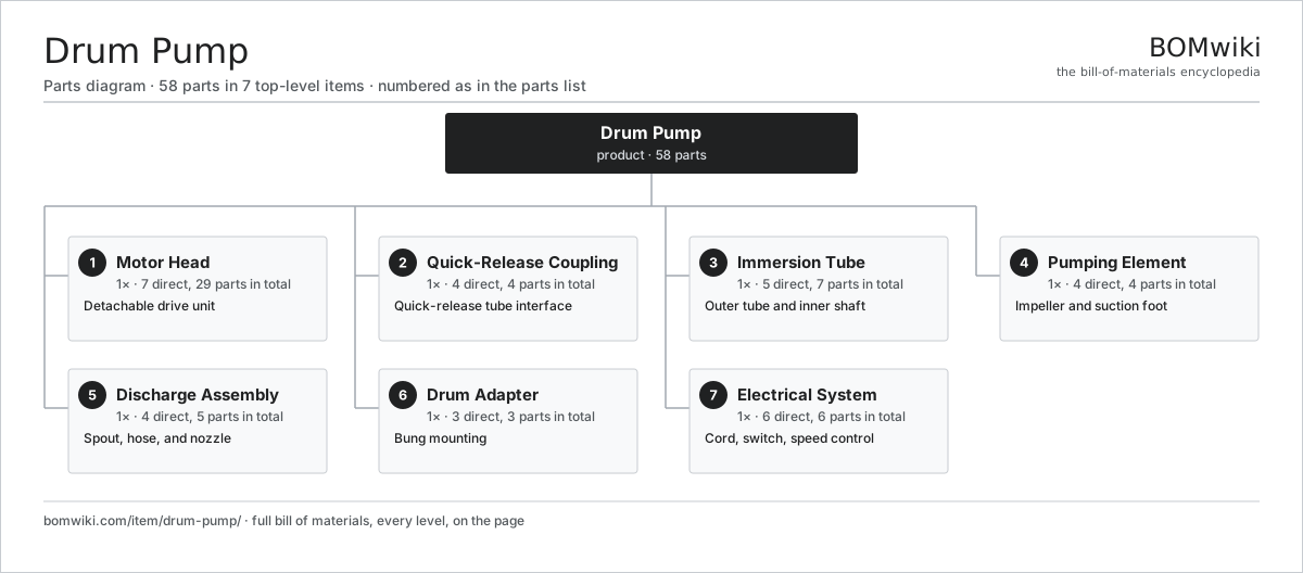
| # | Part | Qty | What it does |
|---|---|---|---|
| 1 | Motor Head 7 parts | 1× | Detachable drive unit |
| 2 | Quick-Release Coupling 4 parts | 1× | Quick-release tube interface |
| 3 | Immersion Tube 5 parts | 1× | Outer tube and inner shaft |
| 4 | Pumping Element 4 parts | 1× | Impeller and suction foot |
| 5 | Discharge Assembly 4 parts | 1× | Spout, hose, and nozzle |
| 6 | Drum Adapter 3 parts | 1× | Bung mounting |
| 7 | Electrical System 6 parts | 1× | Cord, switch, speed control |
3D model
No 3D model yet. Have a CAD file of this? Add a 3D model. STL renders right on this page; STEP, FreeCAD, and OpenSCAD sources are welcome too (openly licensed, like all 3D models on BOMwiki).
Build & assembly graph
expand / collapse · shared sub-assemblies converge · links to related products · est. labourTap an assembly to expand/collapse · tap a part to open it · use “Open page” for any node · drag to pan, scroll to zoom.
Bill of materials for Drum Pump
7 top-level lines · 47 rows shown · 58 parts total · indented to 3 levels| # | Item / sub-assembly | Part no. | Qty/assy | Ext. qty | Parts | Type |
|---|---|---|---|---|---|---|
| 1 | Motor Head 7 parts | drum-pump-motor-head | 1× | 1 | 29 | assembly |
| 1.1 | Motor Housing Shell | drum-pump-motor-housing-shell | 1× | 1 | · | part |
| 1.2 | Stator Assembly 3 parts | stator-assembly | 1× | 1 | 3 | assembly |
| 1.2.1 | Stator Core (laminations) | stator-core | 1× | 1 | · | part |
| 1.2.2 | Copper Winding | copper-winding | 1× | 1 | · | part |
| 1.2.3 | Slot Insulation | stator-insulation | 1× | 1 | · | part |
| 1.3 | Rotor Assembly 4 parts | rotor-assembly | 1× | 1 | 19 | assembly |
| 1.3.1 | Rotor Shaft | rotor-shaft | 1× | 1 | · | part |
| 1.3.2 | Rotor Core | rotor-core | 1× | 1 | · | part |
| 1.3.3 | Neodymium Magnet | neodymium-magnet | 16× | 16 | · | part |
| 1.3.4 | Ball Bearing | ball-bearing | 1× | 1 | · | part |
| 1.4 | Carbon Brush | drum-pump-carbon-brush | 2× | 2 | · | part |
| 1.5 | Cooling Fan | drum-pump-cooling-fan | 1× | 1 | · | part |
| 1.6 | Ball Bearing | ball-bearing | 2× | 2 | · | part |
| 1.7 | Carrying Handle | drum-pump-handle | 1× | 1 | · | part |
| 2 | Quick-Release Coupling 4 parts | drum-pump-coupling | 1× | 1 | 4 | assembly |
| 2.1 | Coupling Hand Nut | drum-pump-coupling-nut | 1× | 1 | · | part |
| 2.2 | Drive Dog | drum-pump-drive-dog | 1× | 1 | · | part |
| 2.3 | Shaft Socket | drum-pump-shaft-socket | 1× | 1 | · | part |
| 2.4 | O-Ring Set | oring-set | 1× | 1 | · | part |
| 3 | Immersion Tube 5 parts | drum-pump-immersion-tube | 1× | 1 | 7 | assembly |
| 3.1 | Outer Tube | drum-pump-outer-tube | 1× | 1 | · | part |
| 3.2 | Inner Shaft | drum-pump-inner-shaft | 1× | 1 | · | part |
| 3.3 | Shaft Bushing | drum-pump-shaft-bushing | 3× | 3 | · | part |
| 3.4 | Foot Strainer | drum-pump-foot-strainer | 1× | 1 | · | part |
| 3.5 | Tube Shaft Seal | drum-pump-tube-seal | 1× | 1 | · | part |
| 4 | Pumping Element 4 parts | drum-pump-pumping-element | 1× | 1 | 4 | assembly |
| 4.1 | Impeller | drum-pump-impeller | 1× | 1 | · | part |
| 4.2 | Suction Foot | drum-pump-suction-foot | 1× | 1 | · | part |
| 4.3 | Impeller Retainer | drum-pump-impeller-retainer | 1× | 1 | · | part |
| 4.4 | O-Ring Set | oring-set | 1× | 1 | · | part |
| 5 | Discharge Assembly 4 parts | drum-pump-discharge-assembly | 1× | 1 | 5 | assembly |
| 5.1 | Discharge Spout | drum-pump-discharge-spout | 1× | 1 | · | part |
| 5.2 | Discharge Hose | drum-pump-discharge-hose | 1× | 1 | · | part |
| 5.3 | Hand Nozzle | drum-pump-hand-nozzle | 1× | 1 | · | part |
| 5.4 | Hose Clamp | drum-pump-hose-clamp | 2× | 2 | · | part |
| 6 | Drum Adapter 3 parts | drum-pump-drum-adapter | 1× | 1 | 3 | assembly |
| 6.1 | Bung Adapter | drum-pump-bung-adapter | 1× | 1 | · | part |
| 6.2 | Adapter Seal | drum-pump-adapter-seal | 1× | 1 | · | part |
| 6.3 | Depth Collar | drum-pump-depth-collar | 1× | 1 | · | part |
| 7 | Electrical System 6 parts | drum-pump-electrical | 1× | 1 | 6 | assembly |
| 7.1 | Power Cord | drum-pump-power-cord | 1× | 1 | · | part |
| 7.2 | Rocker Switch | drum-pump-rocker-switch | 1× | 1 | · | part |
| 7.3 | Speed Control Board | drum-pump-speed-control-board | 1× | 1 | · | part |
| 7.4 | SMD Passive (R/C/L) | smd-passives | 1× | 1 | · | part |
| 7.5 | Wire Bundle | wire-bundle | 1× | 1 | · | part |
| 7.6 | Thermal Fuse | thermal-fuse | 1× | 1 | · | part |
Something wrong in this list? Report a problem with this BOM.
Related products
same domain, ranked by shared parts Canned Motor Pump
74 parts · shares 2 with this page
 Irrigation Pump Station
1,881 parts · shares 2 with this page
Mine Dewatering Pump
259 parts · shares 2 with this page
 Sluice Gate
123 parts · shares 2 with this page
 Butterfly Valve
152 parts · shares 1 with this page
 Centrifugal Compressor
338 parts · shares 1 with this page
Sourcing: possible vendors
Browse the supplier directory → Prices, MOQ, and lead times are algorithmic estimates, not quotes, and not claims about these companies. Company mappings are curated by keyword; est. price band $50–$50k. How estimates work| Vendor | HQ | Specialty | MOQ | Lead time |
|---|---|---|---|---|
|
🇩🇰Grundfos
grundfos.com ↗
|
Bjerringbro, DK | Pumps | 200 units | 6–12 wks |
|
🇺🇸Xylem
xylem.com ↗
|
Washington, US | Water technology | 200 units | 6–12 wks |
| flowserve.com ↗ | Irving, US | Pumps & valves | 200 units | 6–12 wks |
|
🇩🇪KSB
ksb.com ↗
|
Frankenthal, DE | Pumps & valves | 200 units | 6–12 wks |
| parker.com ↗ | Cleveland, US | Motion & fluid control | 200 units | 6–12 wks |
722-word article