FRL Unit
ProductOverview
A filter-regulator-lubricator (FRL) unit is the standard air preparation station in any pneumatic system. These three separate functions are typically housed in one modular stack: the Filter Stage removes water, mist, and solid particulates using a spin-on cartridge; the Regulator Stage stabilizes the outlet pressure; and the Lubricator Stage injects a measured oil mist into the clean, regulated air downstream. Industrial production machinery, labeling lines, and assembly robots all require FRL units to protect cylinders and valves from contamination while extending component life.
How it works
Wet, high-pressure system air enters the Filter Stage and collides with a baffle in the Filter Bowl. Moisture condenses and falls to the bottom; the air then passes through the Filter Cartridge, whose pleated paper element traps solid particles down to 5 μm. A Bypass Valve prevents filter choking at startup: if the pressure drop exceeds 2.5 bar (indicating a saturated cartridge), the valve opens so the Drain Cock can be opened to purge water safely.
The Regulator Stage receives this clean air and reduces it to a user-set outlet pressure (commonly 6 bar). A frl-unit-poppet balanced by a Spring Stack seats against the Valve Seat; when outlet pressure rises above setpoint, the poppet lifts slightly, bleeding excess air to exhaust. The Pressure Gauge, typically a 0–10 bar glycerin-filled analogue gauge, lets the operator verify static outlet pressure. A Relief Valve in parallel cuts off pressure if it overshoots, protecting downstream equipment.
The Lubricator Stage taps off a small fraction of the regulated air as a pilot signal to a Atomizer Nozzle. This venturi action draws oil from the Oil Bottle via the Oil Wick, atomizing it into a fine mist. The Adjustment Screw meters how much air passes through the atomizer; turning it opens the air path, increasing mist. The mist exits with the main air stream, coating cylinders and motor vanes to reduce friction. An Overflow Valve prevents the bottle from over-pressurizing.
Maintenance
The Filter Cartridge requires replacement when water output is high or flow drops noticeably, typically every 500–2000 operating hours depending on air quality. The Oil Bottle should be refilled with ISO VG 32 pneumatic oil when it empties; overfilling causes slugging (liquid droplets exiting instead of mist). The Spring Stack and frl-unit-poppet are calibrated at the factory and rarely need adjustment. If the outlet pressure drifts, check that the adjustment Adjustment Handle has not loosened due to vibration.
FRL Unit parts and their functions
8 top-level parts · 27 parts in total · full bill of materials below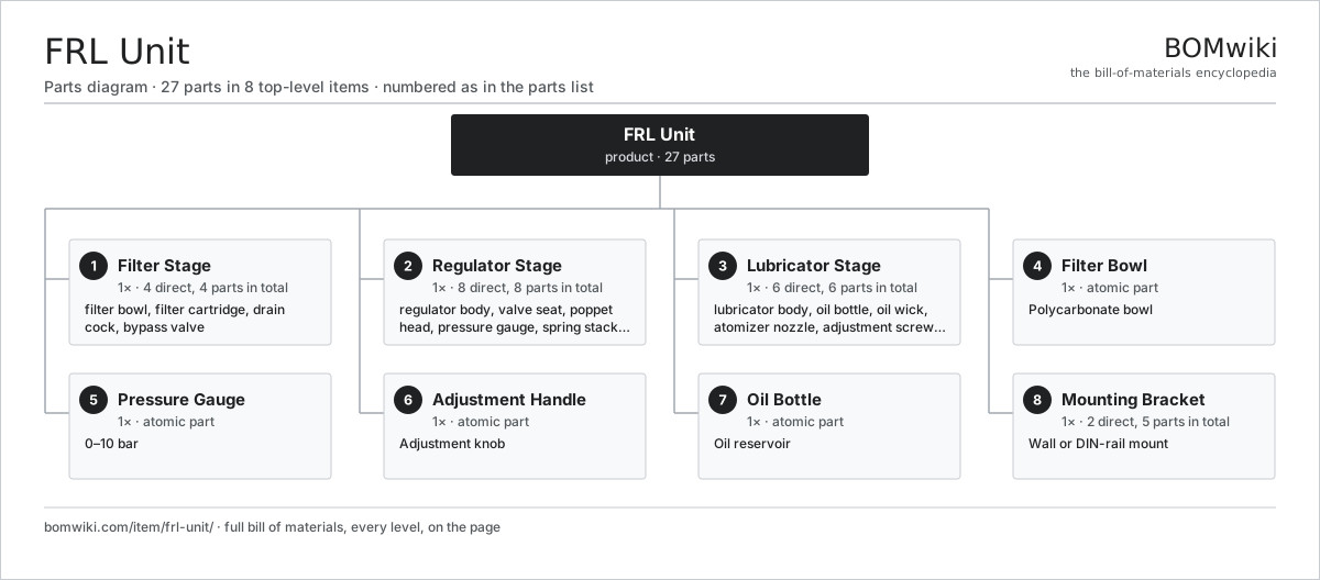
| # | Part | Qty | What it does |
|---|---|---|---|
| 1 | Filter Stage 4 parts | 1× | First stage: 5 μm spin-on cartridge removes water droplets and solid particles. |
| 2 | Regulator Stage 8 parts | 1× | Second stage: pilot-operated regulator maintains constant outlet pressure (0–8 bar adjustable). |
| 3 | Lubricator Stage 6 parts | 1× | Third stage: oil atomizer injects calculated mist into outlet air for piston and cylinder lubrication. |
| 4 | Filter Bowl | 1× | Polycarbonate bowl |
| 5 | Pressure Gauge | 1× | 0–10 bar |
| 6 | Adjustment Handle | 1× | Adjustment knob |
| 7 | Oil Bottle | 1× | Oil reservoir |
| 8 | Mounting Bracket 2 parts | 1× | Wall or DIN-rail mount |
3D model
No 3D model yet. Have a CAD file of this? Add a 3D model. STL renders right on this page; STEP, FreeCAD, and OpenSCAD sources are welcome too (openly licensed, like all 3D models on BOMwiki).
Build & assembly graph
expand / collapse · shared sub-assemblies converge · links to related products · est. labourTap an assembly to expand/collapse · tap a part to open it · use “Open page” for any node · drag to pan, scroll to zoom.
Bill of materials for FRL Unit
8 top-level lines · 28 rows shown · 27 parts total · indented to 3 levels| # | Item / sub-assembly | Part no. | Qty/assy | Ext. qty | Parts | Type |
|---|---|---|---|---|---|---|
| 1 | Filter Stage 4 parts | frl-unit-filter-stage | 1× | 1 | 4 | assembly |
| 1.1 | Filter Bowl | frl-unit-filter-bowl | 1× | 1 | · | part |
| 1.2 | Filter Cartridge | frl-unit-filter-cartridge | 1× | 1 | · | part |
| 1.3 | Drain Cock | frl-unit-drain-cock | 1× | 1 | · | part |
| 1.4 | Bypass Valve | frl-unit-bypass-valve | 1× | 1 | · | part |
| 2 | Regulator Stage 8 parts | frl-unit-regulator-stage | 1× | 1 | 8 | assembly |
| 2.1 | Regulator Body | frl-unit-regulator-body | 1× | 1 | · | part |
| 2.2 | Valve Seat | frl-unit-regulator-seat | 1× | 1 | · | part |
| 2.3 | Poppet Head | frl-unit-regulator-poppet | 1× | 1 | · | part |
| 2.4 | Pressure Gauge | frl-unit-pressure-gauge | 1× | 1 | · | part |
| 2.5 | Spring Stack | frl-unit-regulator-spring | 1× | 1 | · | part |
| 2.6 | Adjustment Handle | frl-unit-regulator-handle | 1× | 1 | · | part |
| 2.7 | Relief Valve | frl-unit-relief-valve | 1× | 1 | · | part |
| 2.8 | Pressure Sensor | pressure-sensor | 1× | 1 | · | part |
| 3 | Lubricator Stage 6 parts | frl-unit-lubricator-stage | 1× | 1 | 6 | assembly |
| 3.1 | Lubricator Body | frl-unit-lubricator-body | 1× | 1 | · | part |
| 3.2 | Oil Bottle | frl-unit-lubricator-bottle | 1× | 1 | · | part |
| 3.3 | Oil Wick | frl-unit-wick-element | 1× | 1 | · | part |
| 3.4 | Atomizer Nozzle | frl-unit-atomizer-nozzle | 1× | 1 | · | part |
| 3.5 | Adjustment Screw | frl-unit-adjustment-screw | 1× | 1 | · | part |
| 3.6 | Overflow Valve | frl-unit-overflow-valve | 1× | 1 | · | part |
| 4 | Filter Bowl | frl-unit-filter-bowl | 1× | 1 | · | part |
| 5 | Pressure Gauge | frl-unit-pressure-gauge | 1× | 1 | · | part |
| 6 | Adjustment Handle | frl-unit-regulator-handle | 1× | 1 | · | part |
| 7 | Oil Bottle | frl-unit-lubricator-bottle | 1× | 1 | · | part |
| 8 | Mounting Bracket 2 parts | frl-unit-bracket-kit | 1× | 1 | 5 | assembly |
| 8.1 | Bracket Arm | frl-unit-bracket-arm | 1× | 1 | · | part |
| 8.2 | Bracket Fastener | frl-unit-bracket-fastener | 4× | 4 | · | part |
Something wrong in this list? Report a problem with this BOM.
Related products
same domain, ranked by shared parts Basket Strainer
39 parts · shares 1 with this page
 Boiler Feedwater Pump
169 parts · shares 1 with this page
 Centrifugal Compressor
338 parts · shares 1 with this page
 Condenser Cooling Water Pump
117 parts · shares 1 with this page
 Control Valve
46 parts · shares 1 with this page
 High-Pressure Plunger Pump
115 parts · shares 1 with this page
Sourcing: possible vendors
Browse the supplier directory → Prices, MOQ, and lead times are algorithmic estimates, not quotes, and not claims about these companies. Company mappings are curated by keyword; est. price band $50–$50k. How estimates work| Vendor | HQ | Specialty | MOQ | Lead time |
|---|---|---|---|---|
|
🇩🇰Grundfos
grundfos.com ↗
|
Bjerringbro, DK | Pumps | 200 units | 6–12 wks |
|
🇺🇸Xylem
xylem.com ↗
|
Washington, US | Water technology | 200 units | 6–12 wks |
| flowserve.com ↗ | Irving, US | Pumps & valves | 200 units | 6–12 wks |
|
🇩🇪KSB
ksb.com ↗
|
Frankenthal, DE | Pumps & valves | 200 units | 6–12 wks |
| parker.com ↗ | Cleveland, US | Motion & fluid control | 200 units | 6–12 wks |
460-word article