Powered Conference Table
ProductOverview
A powered conference table integrates electrical outlets, USB charging, and network connectivity directly into the worksurface through modular cubby inserts, eliminating the need for under-desk power strips or central cord routing. The Worktop Assembly is a laminated particleboard panel, typically 1.8–3.6 m long and 0.9 m deep, routed with four Power/Data Cubby Modules, snap-in power/data hubs positioned at typical seating intervals. Beneath the top, a Under-Top Cable Tray System runs lengthwise, housing the Electrical Harness and Data Harness, converging at a central Power Distribution Block and Network Patch Panel. The Base Frame Assembly supports the top on four Leg Assemblies, which can be manually leveling feet or, on higher-end models, electric height-adjustment cylinders for sit-stand conversion.
The design addresses two pain points in meeting spaces: cable clutter around the perimeter and the sitting-only posture during long calls. Cubbies deliver power and Ethernet at arm's reach without tripping hazards, and powered legs allow groups to alternate between sitting and standing positions using a single control button. Flat-pack logistics make the unit amenable to reconfiguration as team sizes or spaces change.
Power delivery and data
Each cubby module houses two AC outlets and dual USB charging ports, fed in parallel from the under-tray Power Distribution Block. The hub itself is supplied by the main Power Cord (typically 12 AWG, 15 A rated), routed through a grommet and plugged into a wall outlet; a screw-terminal block inside the hub allows wiring of internal taps. Each cubby's mating pigtail runs through the Under-Top Cable Tray System to the hub, so cubbies can be removed or swapped without breaking the main circuit.
Network connectivity comes through the RJ45 jack in each cubby. All four cubbies daisy-chain via Cat6A bulk cable to the Network Patch Panel, which receives its uplink from an external switch. This topology lets meeting rooms dial in to a single network line, with the table acting as a local distribution point, useful for huddle spaces or makeshift team areas that lack individual desk cabling.
Structural and mechanical
The Base Frame Assembly is welded structural steel: two side rails (40 × 60 mm rectangular tube) run the length of the table, joined at each end by Base Cross Members. Diagonal or continuous bracing in the mid-span resists racking when the table is pushed or pulled. Four columns bolt onto the frame through Top Mount Plates welded to the rails; each leg supports roughly 150–200 kg, enabling a distributed load of 600–800 kg.
Static legs use adjustable screw feet or elastomer pads for floor levelling. Electric models substitute linear lift cylinders, fed 24 V DC by the main Electrical Harness and triggered by a hardwired or wireless height-control button, typically located at one end of the table for synchronized twin-leg rise. The upstroke is smooth (about 2–3 cm/s) so papers and devices don't slide; limit switches at 72 cm and 120 cm prevent over-travel.
The Under-Top Cable Tray System hangs from Tray Support Brackets welded to the base rails, positioned 150–200 mm below the top. This spacing is tight enough to accommodate the under-panel stiffening frame and loose enough for technicians to pull and route cables by hand. The tray is typically perforated 12 mm steel or stainless wire basket, minimizing the shadow it casts under the table and letting heat from active hubs dissipate.
Installation and maintenance
The Worktop Assembly is routed with four rectangular knock-outs (100 × 100 mm typical) at standard 600–800 mm spacing, into which the Power/Data Cubby Modules press-fit and snap with spring latches. If a cubby fails, it can be unsnapped in seconds and a replacement (or blank cover) inserted; the electrical connector is a simple quick-disconnect, so no soldering is needed. The internal harness is dressed in the tray with cable ties; if the main power cord needs replacement, the Terminal Block is accessible from below.
Network jacks use standard RJ45 crimps at each cubby pigtail. The Network Patch Panel sits in the tray at one end of the table and is typically terminated to an external cabinet; management of which desk has which vlan or IP block falls to the IT operator of the patch panel, not the table itself. Labelling the cubbies (1, 2, 3, 4 from left to right) is essential for network mapping.
Electric height adjustment adds complexity but enables standing meetings without a second table. The height-control button is wired to a simple relay or PWM module that energizes both lift cylinders simultaneously; individual synchronization springs or microswitches ensure both sides rise at the same speed. A typical electrically-powered table adds 8–12 kg to the weight and requires a 24 V auxiliary supply tapped from the main PSU inside the hub (rare; most designs rely on a small separate 24 V brick plugged beside the main cord).
Finish and aesthetics
The Top Panel is usually laminated particleboard in matte or gloss finishes, white, grey, teak, or walnut veneer, chosen to match surrounding office furniture. The edge banding is thermofused PVC or matching veneer to hide the core. The Base Frame Assembly is typically powder-coated matte black, gunmetal grey, or silver, and stainless-steel cubbies or anodized aluminium are available for premium specifications.
Powered Conference Table parts and their functions
9 top-level parts · 122 parts in total · full bill of materials below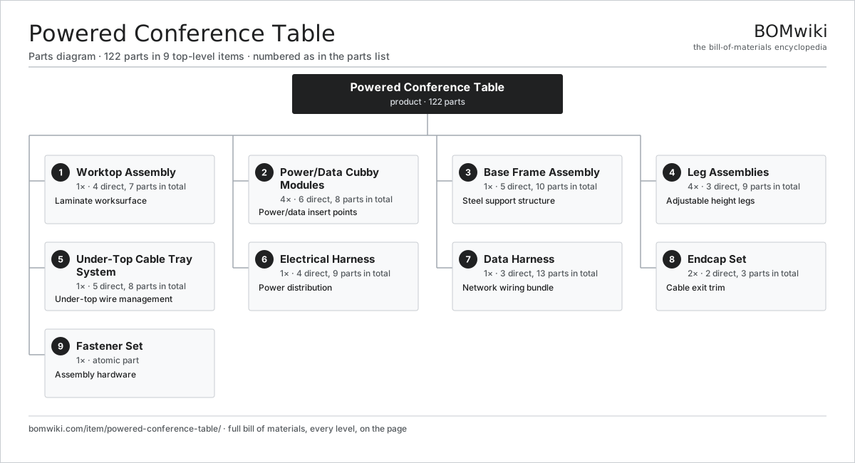
| # | Part | Qty | What it does |
|---|---|---|---|
| 1 | Worktop Assembly 4 parts | 1× | Laminate worksurface |
| 2 | Power/Data Cubby Modules 6 parts | 4× | Power/data insert points |
| 3 | Base Frame Assembly 5 parts | 1× | Steel support structure |
| 4 | Leg Assemblies 3 parts | 4× | Adjustable height legs |
| 5 | Under-Top Cable Tray System 5 parts | 1× | Under-top wire management |
| 6 | Electrical Harness 4 parts | 1× | Power distribution |
| 7 | Data Harness 3 parts | 1× | Network wiring bundle |
| 8 | Endcap Set 2 parts | 2× | Cable exit trim |
| 9 | Fastener Set | 1× | Assembly hardware |
3D model
No 3D model yet. Have a CAD file of this? Add a 3D model. STL renders right on this page; STEP, FreeCAD, and OpenSCAD sources are welcome too (openly licensed, like all 3D models on BOMwiki).
Build & assembly graph
expand / collapse · shared sub-assemblies converge · links to related products · est. labourTap an assembly to expand/collapse · tap a part to open it · use “Open page” for any node · drag to pan, scroll to zoom.
Bill of materials for Powered Conference Table
9 top-level lines · 41 rows shown · 122 parts total · indented to 3 levels| # | Item / sub-assembly | Part no. | Qty/assy | Ext. qty | Parts | Type |
|---|---|---|---|---|---|---|
| 1 | Worktop Assembly 4 parts | powered-conference-table-top | 1× | 1 | 7 | assembly |
| 1.1 | Top Panel | powered-conference-table-top-panel | 1× | 1 | · | part |
| 1.2 | Edge Banding | powered-conference-table-top-edge-band | 1× | 1 | · | part |
| 1.3 | Under-Top Frame | powered-conference-table-top-frame | 1× | 1 | · | part |
| 1.4 | Cubby Routing | powered-conference-table-cubby-opening | 4× | 4 | · | part |
| 2 | Power/Data Cubby Modules 6 parts | powered-conference-table-cubby-modules | 4× | 4 | 8 | assembly |
| 2.1 | Cubby Housing | powered-conference-table-cubby-housing | 1× | 4 | · | part |
| 2.2 | Power Outlet | powered-conference-table-power-socket | 2× | 8 | · | part |
| 2.3 | USB Charging Port | powered-conference-table-usb-socket | 2× | 8 | · | part |
| 2.4 | Ethernet Jack | powered-conference-table-rj45-socket | 1× | 4 | · | part |
| 2.5 | Cubby Latch | powered-conference-table-cubby-latch | 1× | 4 | · | part |
| 2.6 | Connector | connector | 1× | 4 | · | part |
| 3 | Base Frame Assembly 5 parts | powered-conference-table-base-frame | 1× | 1 | 10 | assembly |
| 3.1 | Base Side Rail | powered-conference-table-base-rail | 2× | 2 | · | part |
| 3.2 | Base Cross Member | powered-conference-table-base-cross-member | 2× | 2 | · | part |
| 3.3 | Base Bracing | powered-conference-table-base-bracing | 1× | 1 | · | part |
| 3.4 | Top Mount Plate | powered-conference-table-top-mount-plate | 4× | 4 | · | part |
| 3.5 | Cable Tray Shelf | powered-conference-table-cable-tray-shelf | 1× | 1 | · | part |
| 4 | Leg Assemblies 3 parts | powered-conference-table-legs | 4× | 4 | 9 | assembly |
| 4.1 | Leg Column | powered-conference-table-leg-column | 4× | 16 | · | part |
| 4.2 | Leg Foot | powered-conference-table-leg-base-foot | 4× | 16 | · | part |
| 4.3 | Height Control | powered-conference-table-leg-adjustment-control | 1× | 4 | · | part |
| 5 | Under-Top Cable Tray System 5 parts | powered-conference-table-cable-tray | 1× | 1 | 8 | assembly |
| 5.1 | Tray Body | powered-conference-table-tray-body | 1× | 1 | · | part |
| 5.2 | Power Distribution Block | powered-conference-table-power-distribution-hub | 1× | 1 | · | part |
| 5.3 | USB Charging Hub | powered-conference-table-usb-charging-hub | 1× | 1 | · | part |
| 5.4 | Network Patch Panel | powered-conference-table-network-patch-panel | 1× | 1 | · | part |
| 5.5 | Tray Support Bracket | powered-conference-table-tray-support-bracket | 4× | 4 | · | part |
| 6 | Electrical Harness 4 parts | powered-conference-table-electrical-harness | 1× | 1 | 9 | assembly |
| 6.1 | Power Cord | powered-conference-table-power-cable | 1× | 1 | · | part |
| 6.2 | Internal Distribution Wire | powered-conference-table-distribution-wire | 1× | 1 | · | part |
| 6.3 | Terminal Block | powered-conference-table-terminal-block | 1× | 1 | · | part |
| 6.4 | Connector | connector | 6× | 6 | · | part |
| 7 | Data Harness 3 parts | powered-conference-table-data-harness | 1× | 1 | 13 | assembly |
| 7.1 | Bulk Ethernet Cable | powered-conference-table-rj45-bulk-cable | 1× | 1 | · | part |
| 7.2 | Terminated RJ45 Pairs | powered-conference-table-rj45-terminated-pairs | 4× | 4 | · | part |
| 7.3 | Cable Boot Set | powered-conference-table-cable-boot-set | 8× | 8 | · | part |
| 8 | Endcap Set 2 parts | powered-conference-table-endcap-set | 2× | 2 | 3 | assembly |
| 8.1 | End Cap | powered-conference-table-endcap | 2× | 4 | · | part |
| 8.2 | Cable Grommet | powered-conference-table-cable-grommet | 1× | 2 | · | part |
| 9 | Fastener Set | fastener-set | 1× | 1 | · | part |
Something wrong in this list? Report a problem with this BOM.
Related products
same domain, ranked by shared parts Adjustable Bed Base
173 parts · shares 1 with this page
Cinema Recliner Seating
61 parts · shares 1 with this page
 Hotel Minibar
79 parts · shares 1 with this page
 Massage Chair
175 parts · shares 1 with this page
Motorized Standing Desk
110 parts · shares 1 with this page
Pedicure Spa Chair
126 parts · shares 1 with this page
Sourcing: possible vendors
Browse the supplier directory → Prices, MOQ, and lead times are algorithmic estimates, not quotes, and not claims about these companies. Company mappings are curated by keyword; est. price band $50–$3k. How estimates work| Vendor | HQ | Specialty | MOQ | Lead time |
|---|---|---|---|---|
| steelcase.com ↗ | Grand Rapids, US | Office furniture | 200 units | 6–12 wks |
| millerknoll.com ↗ | Zeeland, US | Furniture (Herman Miller) | 200 units | 6–12 wks |
|
🇺🇸Haworth
haworth.com ↗
|
Holland, US | Office furniture | 200 units | 6–12 wks |
|
🇺🇸HNI
hnicorp.com ↗
|
Muscatine, US | Furniture & hearth | 200 units | 6–12 wks |
| ikea.com ↗ | Älmhult, SE | Furniture manufacturing | 200 units | 6–12 wks |
1,044-word article