Rotary Vane Pump
ProductOverview
A rotary vane pump moves liquid by trapping it in chambers that grow and shrink as a vaned rotor spins inside an offset ring. Because each turn displaces a fixed volume regardless of pressure, flow stays nearly constant and almost pulse-free, and the pump primes itself by pulling a vacuum at the inlet. Those traits make it a common choice for fuel transfer, light oils, solvents, refrigerants, and the vacuum stage of many machines.
The heart is the Cam Ring & Rotor, where the vanes sweep fluid around the Cam Ring. The End Plates & Shaft closes the chamber ends and carries the shaft, the Ports & Relief Valve times the suction and discharge and caps the pressure, and the Drive Motor spins the whole thing through the Shaft Coupling. The Pump Housing forms the wetted casing and the O-Ring Set seals it.
How it works
The Slotted Rotor is mounted off-centre inside the Cam Ring, so the gap between rotor and ring is large on one side and nearly closed on the other. Radial Sliding Vane blades slide out of their slots and ride the ring bore, helped out by the Coil Spring behind each and by centrifugal force once spinning. Each pair of vanes seals a pocket; as the rotor turns, that pocket expands on the inlet side and draws fluid in, then contracts on the outlet side and pushes it out. Lapped End Plate faces seal the pocket ends and set the running clearance that keeps internal leakage, slip, low.
Because the pump will keep building pressure into a blocked line until something gives, the Relief Valve sits across the ports: its Relief Poppet lifts against a spring once discharge pressure exceeds the set point and dumps flow back to suction. The Drive Shaft runs on Ball Bearing supports with an Oil Seal keeping fluid off the drive end, and the Port Plate aligns its kidney-shaped openings with the expanding and contracting chambers so suction and discharge are correctly timed. Vane pumps are valued for handling thin, low- lubricity fluids that would slip past a gear pump, and the vanes self-compensate for wear as they slide further out over time.
Rotary Vane Pump parts and their functions
8 top-level parts · 57 parts in total · full bill of materials below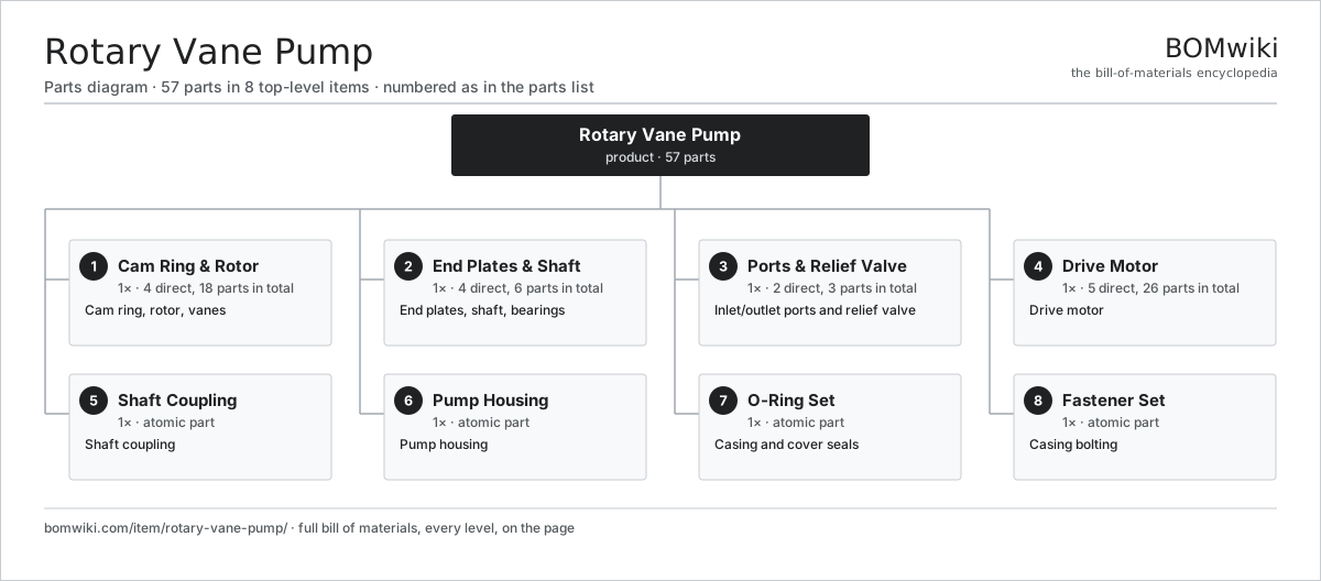
| # | Part | Qty | What it does |
|---|---|---|---|
| 1 | Cam Ring & Rotor 4 parts | 1× | Cam ring, rotor, vanes |
| 2 | End Plates & Shaft 4 parts | 1× | End plates, shaft, bearings |
| 3 | Ports & Relief Valve 2 parts | 1× | Inlet/outlet ports and relief valve |
| 4 | Drive Motor 5 parts | 1× | Drive motor |
| 5 | Shaft Coupling | 1× | Shaft coupling |
| 6 | Pump Housing | 1× | Pump housing |
| 7 | O-Ring Set | 1× | Casing and cover seals |
| 8 | Fastener Set | 1× | Casing bolting |
3D model
No 3D model yet. Have a CAD file of this? Add a 3D model. STL renders right on this page; STEP, FreeCAD, and OpenSCAD sources are welcome too (openly licensed, like all 3D models on BOMwiki).
Build & assembly graph
expand / collapse · shared sub-assemblies converge · links to related products · est. labourTap an assembly to expand/collapse · tap a part to open it · use “Open page” for any node · drag to pan, scroll to zoom.
Bill of materials for Rotary Vane Pump
8 top-level lines · 32 rows shown · 57 parts total · indented to 3 levels| # | Item / sub-assembly | Part no. | Qty/assy | Ext. qty | Parts | Type |
|---|---|---|---|---|---|---|
| 1 | Cam Ring & Rotor 4 parts | rvp-cam-rotor-assy | 1× | 1 | 18 | assembly |
| 1.1 | Cam Ring | rvp-cam-ring | 1× | 1 | · | part |
| 1.2 | Slotted Rotor | rvp-rotor | 1× | 1 | · | part |
| 1.3 | Sliding Vane | rvp-vane | 8× | 8 | · | part |
| 1.4 | Coil Spring | coil-spring | 8× | 8 | · | part |
| 2 | End Plates & Shaft 4 parts | rvp-endplate-assy | 1× | 1 | 6 | assembly |
| 2.1 | End Plate | rvp-end-plate | 2× | 2 | · | part |
| 2.2 | Drive Shaft | rvp-shaft | 1× | 1 | · | part |
| 2.3 | Ball Bearing | ball-bearing | 2× | 2 | · | part |
| 2.4 | Oil Seal | oil-seal | 1× | 1 | · | part |
| 3 | Ports & Relief Valve 2 parts | rvp-port-assy | 1× | 1 | 3 | assembly |
| 3.1 | Port Plate | rvp-port-plate | 1× | 1 | · | part |
| 3.2 | Relief Valve 2 parts | rvp-relief-valve | 1× | 1 | 2 | assembly |
| 3.2.1 | Relief Poppet | rvp-relief-poppet | 1× | 1 | · | part |
| 3.2.2 | Coil Spring | coil-spring | 1× | 1 | · | part |
| 4 | Drive Motor 5 parts | rvp-motor-assy | 1× | 1 | 26 | assembly |
| 4.1 | Stator Assembly 3 parts | stator-assembly | 1× | 1 | 3 | assembly |
| 4.1.1 | Stator Core (laminations) | stator-core | 1× | 1 | · | part |
| 4.1.2 | Copper Winding | copper-winding | 1× | 1 | · | part |
| 4.1.3 | Slot Insulation | stator-insulation | 1× | 1 | · | part |
| 4.2 | Rotor Assembly 4 parts | rotor-assembly | 1× | 1 | 19 | assembly |
| 4.2.1 | Rotor Shaft | rotor-shaft | 1× | 1 | · | part |
| 4.2.2 | Rotor Core | rotor-core | 1× | 1 | · | part |
| 4.2.3 | Neodymium Magnet | neodymium-magnet | 16× | 16 | · | part |
| 4.2.4 | Ball Bearing | ball-bearing | 1× | 1 | · | part |
| 4.3 | Copper Winding | copper-winding | 1× | 1 | · | part |
| 4.4 | Motor Housing | motor-housing | 1× | 1 | · | part |
| 4.5 | Ball Bearing | ball-bearing | 2× | 2 | · | part |
| 5 | Shaft Coupling | rvp-coupling | 1× | 1 | · | part |
| 6 | Pump Housing | rvp-housing | 1× | 1 | · | part |
| 7 | O-Ring Set | oring-set | 1× | 1 | · | part |
| 8 | Fastener Set | fastener-set | 1× | 1 | · | part |
Something wrong in this list? Report a problem with this BOM.
Related products
same domain, ranked by shared parts High-Pressure Plunger Pump
115 parts · shares 3 with this page
 Hydraulic Power Unit
91 parts · shares 3 with this page
 Irrigation Pump Station
1,881 parts · shares 2 with this page
 Mainline Pipeline Pump
166 parts · shares 2 with this page
 Three-Screw Pump
42 parts · shares 2 with this page
Hydraulic Test Bench
77 parts · shares 2 with this page
Sourcing: possible vendors
Browse the supplier directory → Prices, MOQ, and lead times are algorithmic estimates, not quotes, and not claims about these companies. Company mappings are curated by keyword; est. price band $50–$50k. How estimates work| Vendor | HQ | Specialty | MOQ | Lead time |
|---|---|---|---|---|
|
🇩🇰Grundfos
grundfos.com ↗
|
Bjerringbro, DK | Pumps | 200 units | 6–12 wks |
|
🇺🇸Xylem
xylem.com ↗
|
Washington, US | Water technology | 200 units | 6–12 wks |
| flowserve.com ↗ | Irving, US | Pumps & valves | 200 units | 6–12 wks |
|
🇩🇪KSB
ksb.com ↗
|
Frankenthal, DE | Pumps & valves | 200 units | 6–12 wks |
| parker.com ↗ | Cleveland, US | Motion & fluid control | 200 units | 6–12 wks |
373-word article