EOD Robot
ProductOverview
An EOD (explosive ordnance disposal) robot exists to put distance between a bomb technician and a bomb. Render-safe procedures that once required a walk downrange in an 40 kg blast suit, inspecting a device, cutting into it, placing a disruptor, are instead performed by a tracked vehicle under remote control, while the operator stands behind cover hundreds of meters away. The robot is expendable by doctrine: losing a machine to detonation is a successful outcome compared with the alternative.
The platform divides into a mobility base, the Tracked Chassis; a dexterous Manipulator Arm; the Camera Suite that serves as the operator's eyes; a Operator Control Station and Communications System system linking human to machine; the Power System; the Disruptor Mount for actually defeating a device; and the Electronics Bay that coordinates everything.
Mobility
The Hull is a sealed aluminum tub with batteries mounted low, because the governing mobility problem is stairs: the robot must climb 40-degree stairways without pitching over backward. Each Track Unit is a Kevlar-reinforced Rubber Track driven skid-steer style by its own Drive Motor Unit, a brushless motor and planetary gearset of roughly 500 W per side. The Flipper Arm pair at the front rotates independently through a full circle, extended forward they lengthen the effective wheelbase to bridge stair nosings and ditches, and swept fully over they can lever the robot back onto its tracks after a rollover, since no one can walk downrange to flip it.
Manipulation
The Manipulator Arm trades speed for precision and holding ability. Each major joint, Shoulder Joint, Elbow Joint, Wrist Module, uses a Harmonic Drive Unit strain-wave gearbox at around 100:1 reduction, chosen because harmonic drives have essentially zero backlash: when the operator stops commanding motion, the arm holds position exactly, which matters when the gripper is an inch from a tripwire. The Gripper closes its jaws through a Ball Screw so that motor current maps smoothly to grip force, read back by a Pressure Sensor; the same end effector that crushes a car window can pick up a single detonator wire. Jaws are deliberately sacrificial, when a device functions during manipulation, the gripper takes the blast first and is replaced as a module.
Seeing and driving
Teleoperation succeeds or fails on video. Wide-angle Drive Camera units front and rear give driving context; the mast-mounted PTZ Zoom Camera carries 30x or greater optical zoom so the technician can read wiring, switches, and markings from stand-off; the Gripper Camera looks straight down the jaw axis for fine work; and the Thermal Imager reveals warm electronics or recently handled objects. All feeds pass through the Video Encoder, which must hold end-to-end latency under about 150 ms, beyond that, closed-loop manipulation becomes guesswork.
Control link
The primary link is the RF Radio Module, an AES-encrypted COFDM or mesh-IP radio good for 800-1000 m line of sight. But EOD teams routinely operate under their own electronic countermeasures, jammers intended to block radio-triggered devices also jam the robot, so the Fiber-Optic Spooler pays out a few hundred meters of single-mode fiber as a tether that is immune to jamming and emits nothing. The Main Computer enforces lost-link behavior: if both links drop, the robot stops, locks the arm, and waits rather than executing any autonomous motion near a device.
Defeating the device
Most render-safe shots use a water disruptor, a barrel that fires a slug of water at high velocity to tear a device apart faster than its fuzing can react. The Disruptor Rail clamps the disruptor in line with the wrist; the Laser Aimer is boresighted to mark the impact point in the camera view; the Recoil Buffer soaks up several kilonewtons of recoil that would otherwise destroy the arm's gearing. The Remote Firing Circuit is dual-interlocked: arming and firing are separate deliberate actions at the console, electrically isolated until commanded, so no software fault or link glitch can fire the shot.
Power and endurance
Two hot-swappable Battery Pack modules of 500-700 Wh each feed a 24-48 V bus through the Power Distribution Board board, giving 2-6 hours depending on how much driving and arm work the task demands. Hot-swap matters operationally: a long render-safe procedure cannot pause for a charge cycle, so depleted packs are exchanged in seconds during a planned return to cover.
EOD Robot parts and their functions
8 top-level parts · 1,224 parts in total · full bill of materials below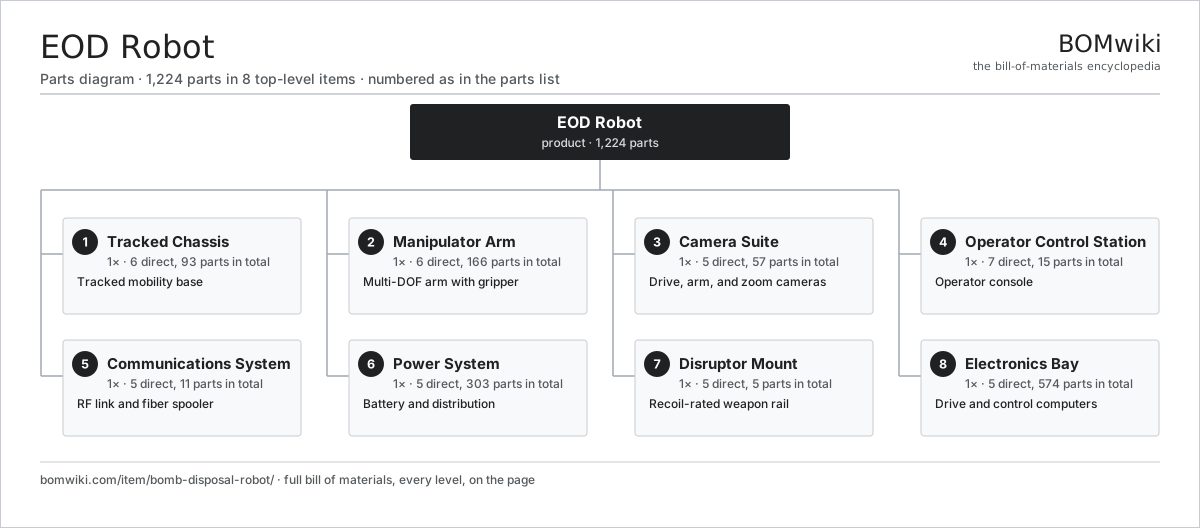
| # | Part | Qty | What it does |
|---|---|---|---|
| 1 | Tracked Chassis 6 parts | 1× | Tracked mobility base |
| 2 | Manipulator Arm 6 parts | 1× | Multi-DOF arm with gripper |
| 3 | Camera Suite 5 parts | 1× | Drive, arm, and zoom cameras |
| 4 | Operator Control Station 7 parts | 1× | Operator console |
| 5 | Communications System 5 parts | 1× | RF link and fiber spooler |
| 6 | Power System 5 parts | 1× | Battery and distribution |
| 7 | Disruptor Mount 5 parts | 1× | Recoil-rated weapon rail |
| 8 | Electronics Bay 5 parts | 1× | Drive and control computers |
Diagrams & photos

3D model
No 3D model yet. Have a CAD file of this? Add a 3D model. STL renders right on this page; STEP, FreeCAD, and OpenSCAD sources are welcome too (openly licensed, like all 3D models on BOMwiki).
Build & assembly graph
expand / collapse · shared sub-assemblies converge · links to related products · est. labourTap an assembly to expand/collapse · tap a part to open it · use “Open page” for any node · drag to pan, scroll to zoom.
Bill of materials for EOD Robot
8 top-level lines · 100 rows shown · 1,224 parts total · indented to 3 levels| # | Item / sub-assembly | Part no. | Qty/assy | Ext. qty | Parts | Type |
|---|---|---|---|---|---|---|
| 1 | Tracked Chassis 6 parts | bdr-chassis | 1× | 1 | 93 | assembly |
| 1.1 | Hull | bdr-hull | 1× | 1 | · | part |
| 1.2 | Track Unit 5 parts | bdr-track-unit | 2× | 2 | 11 | assembly |
| 1.2.1 | Rubber Track | bdr-rubber-track | 1× | 2 | · | part |
| 1.2.2 | Drive Sprocket | bdr-drive-sprocket | 1× | 2 | · | part |
| 1.2.3 | Road Wheel | bdr-road-wheel | 4× | 8 | · | part |
| 1.2.4 | Track Tensioner | bdr-track-tensioner | 1× | 2 | · | part |
| 1.2.5 | Ball Bearing | ball-bearing | 4× | 8 | · | part |
| 1.3 | Flipper Arm | bdr-flipper-arm | 2× | 2 | · | part |
| 1.4 | Drive Motor Unit 6 parts | bdr-drive-motor | 2× | 2 | 28 | assembly |
| 1.4.1 | Stator Assembly 3 parts + deeper › | stator-assembly | 1× | 2 | 3 | assembly |
| 1.4.2 | Rotor Assembly 4 parts + deeper › | rotor-assembly | 1× | 2 | 19 | assembly |
| 1.4.3 | Gearbox Housing | gearbox-housing | 1× | 2 | · | part |
| 1.4.4 | Helical Gear Pair | gear-pair | 3× | 6 | · | part |
| 1.4.5 | Encoder | encoder | 1× | 2 | · | part |
| 1.4.6 | Motor Housing | motor-housing | 1× | 2 | · | part |
| 1.5 | Ball Bearing | ball-bearing | 8× | 8 | · | part |
| 1.6 | Oil Seal | oil-seal | 4× | 4 | · | part |
| 2 | Manipulator Arm 6 parts | bdr-manipulator | 1× | 1 | 166 | assembly |
| 2.1 | Shoulder Joint 4 parts | bdr-shoulder-joint | 1× | 1 | 54 | assembly |
| 2.1.1 | Servo Motor 4 parts + deeper › | servo-motor | 2× | 2 | 24 | assembly |
| 2.1.2 | Harmonic Drive Unit | bdr-harmonic-drive | 2× | 2 | · | part |
| 2.1.3 | Encoder | encoder | 2× | 2 | · | part |
| 2.1.4 | Oil Seal | oil-seal | 2× | 2 | · | part |
| 2.2 | Arm Link | bdr-arm-link | 2× | 2 | · | part |
| 2.3 | Elbow Joint 4 parts | bdr-elbow-joint | 1× | 1 | 27 | assembly |
| 2.3.1 | Servo Motor 4 parts + deeper › | servo-motor | 1× | 1 | 24 | assembly |
| 2.3.2 | Harmonic Drive Unit | bdr-harmonic-drive | 1× | 1 | · | part |
| 2.3.3 | Encoder | encoder | 1× | 1 | · | part |
| 2.3.4 | Hall Sensor | hall-sensor | 1× | 1 | · | part |
| 2.4 | Wrist Module 4 parts | bdr-wrist-module | 1× | 1 | 53 | assembly |
| 2.4.1 | Servo Motor 4 parts + deeper › | servo-motor | 2× | 2 | 24 | assembly |
| 2.4.2 | Helical Gear Pair | gear-pair | 2× | 2 | · | part |
| 2.4.3 | Encoder | encoder | 2× | 2 | · | part |
| 2.4.4 | O-Ring Set | oring-set | 1× | 1 | · | part |
| 2.5 | Gripper 5 parts | bdr-gripper | 1× | 1 | 29 | assembly |
| 2.5.1 | Gripper Jaw | bdr-gripper-jaw | 2× | 2 | · | part |
| 2.5.2 | Servo Motor 4 parts + deeper › | servo-motor | 1× | 1 | 24 | assembly |
| 2.5.3 | Ball Screw | ball-screw | 1× | 1 | · | part |
| 2.5.4 | Pressure Sensor | pressure-sensor | 1× | 1 | · | part |
| 2.5.5 | Gripper Camera Bracket | bdr-gripper-camera-bracket | 1× | 1 | · | part |
| 2.6 | Wire Bundle | wire-bundle | 1× | 1 | · | part |
| 3 | Camera Suite 5 parts | bdr-camera-suite | 1× | 1 | 57 | assembly |
| 3.1 | PTZ Zoom Camera 4 parts | bdr-ptz-camera | 1× | 1 | 51 | assembly |
| 3.1.1 | CMOS Image Sensor | image-sensor | 1× | 1 | · | part |
| 3.1.2 | Lens Assembly | camera-lens | 1× | 1 | · | part |
| 3.1.3 | Servo Motor 4 parts + deeper › | servo-motor | 2× | 2 | 24 | assembly |
| 3.1.4 | Bare PCB | pcb-bare | 1× | 1 | · | part |
| 3.2 | Drive Camera | bdr-drive-camera | 2× | 2 | · | part |
| 3.3 | Gripper Camera | bdr-gripper-camera | 1× | 1 | · | part |
| 3.4 | Thermal Imager | bdr-thermal-camera | 1× | 1 | · | part |
| 3.5 | LED Illuminator | bdr-led-illuminator | 2× | 2 | · | part |
| 4 | Operator Control Station 7 parts | bdr-control-station | 1× | 1 | 15 | assembly |
| 4.1 | OCU Case | bdr-ocu-case | 1× | 1 | · | part |
| 4.2 | OCU Display | bdr-ocu-display | 1× | 1 | · | part |
| 4.3 | Hand Controller | bdr-hand-controller | 2× | 2 | · | part |
| 4.4 | Compute SoC Module | soc-module | 1× | 1 | · | part |
| 4.5 | LiPo Cell | lipo-cell | 8× | 8 | · | part |
| 4.6 | Speaker | speaker | 1× | 1 | · | part |
| 4.7 | Touch Digitizer | touch-digitizer | 1× | 1 | · | part |
| 5 | Communications System 5 parts | bdr-comms | 1× | 1 | 11 | assembly |
| 5.1 | RF Radio Module | bdr-radio-module | 1× | 1 | · | part |
| 5.2 | Antenna | bdr-antenna | 2× | 2 | · | part |
| 5.3 | Fiber-Optic Spooler | bdr-fiber-spooler | 1× | 1 | · | part |
| 5.4 | Video Encoder | bdr-video-encoder | 1× | 1 | · | part |
| 5.5 | Connector | connector | 6× | 6 | · | part |
| 6 | Power System 5 parts | bdr-power-system | 1× | 1 | 303 | assembly |
| 6.1 | Battery Pack 4 parts | bdr-battery-pack | 2× | 2 | 63 | assembly |
| 6.1.1 | Li-ion Cell, 18650 | li-cell-18650 | 60× | 120 | · | part |
| 6.1.2 | BMS Board | bms-board | 1× | 2 | · | part |
| 6.1.3 | Connector | connector | 1× | 2 | · | part |
| 6.1.4 | Sheet Metal Panel | sheet-panel | 1× | 2 | · | part |
| 6.2 | BMS Board | bms-board | 2× | 2 | · | part |
| 6.3 | Power Distribution Board 4 parts | bdr-power-distribution | 1× | 1 | 171 | assembly |
| 6.3.1 | Bare PCB | pcb-bare | 1× | 1 | · | part |
| 6.3.2 | Power MOSFET | mosfet | 12× | 12 | · | part |
| 6.3.3 | SMD Passive (R/C/L) | smd-passives | 150× | 150 | · | part |
| 6.3.4 | Connector | connector | 8× | 8 | · | part |
| 6.4 | Relay | relay | 2× | 2 | · | part |
| 6.5 | Thermal Fuse | thermal-fuse | 2× | 2 | · | part |
| 7 | Disruptor Mount 5 parts | bdr-disruptor-mount | 1× | 1 | 5 | assembly |
| 7.1 | Disruptor Rail | bdr-disruptor-rail | 1× | 1 | · | part |
| 7.2 | Recoil Buffer | bdr-recoil-buffer | 1× | 1 | · | part |
| 7.3 | Remote Firing Circuit | bdr-firing-circuit | 1× | 1 | · | part |
| 7.4 | Laser Aimer | bdr-laser-aimer | 1× | 1 | · | part |
| 7.5 | Fastener Set | fastener-set | 1× | 1 | · | part |
| 8 | Electronics Bay 5 parts | bdr-electronics-bay | 1× | 1 | 574 | assembly |
| 8.1 | Main Computer 4 parts | bdr-main-computer | 1× | 1 | 208 | assembly |
| 8.1.1 | Compute SoC Module | soc-module | 1× | 1 | · | part |
| 8.1.2 | Bare PCB | pcb-bare | 1× | 1 | · | part |
| 8.1.3 | SMD Passive (R/C/L) | smd-passives | 200× | 200 | · | part |
| 8.1.4 | Connector | connector | 6× | 6 | · | part |
| 8.2 | Motor Controller 4 parts | bdr-motor-controller | 4× | 4 | 88 | assembly |
| 8.2.1 | Bare PCB | pcb-bare | 1× | 4 | · | part |
| 8.2.2 | Power MOSFET | mosfet | 6× | 24 | · | part |
| 8.2.3 | Microcontroller | mcu | 1× | 4 | · | part |
| 8.2.4 | SMD Passive (R/C/L) | smd-passives | 80× | 320 | · | part |
| 8.3 | Inertial Measurement Unit | bdr-imu | 1× | 1 | · | part |
| 8.4 | Wire Bundle | wire-bundle | 1× | 1 | · | part |
| 8.5 | Connector | connector | 12× | 12 | · | part |
Something wrong in this list? Report a problem with this BOM.
Related products
same domain, ranked by shared parts Optronic Periscope Mast
369 parts · shares 21 with this page
Military Reconnaissance UAV
123 parts · shares 18 with this page
 Ground Surveillance Radar
70 parts · shares 17 with this page
 Minesweeper
1,296 parts · shares 20 with this page
 Self-Propelled Howitzer
848 parts · shares 19 with this page
 Ruggedized Field Laptop
94 parts · shares 5 with this page
Sourcing: possible vendors
Browse the supplier directory → Prices, MOQ, and lead times are algorithmic estimates, not quotes, and not claims about these companies. Company mappings are curated by keyword; est. price band $200–$100M. How estimates work| Vendor | HQ | Specialty | MOQ | Lead time |
|---|---|---|---|---|
| smithsdetection.com ↗ | London, GB | Security screening | made to order | 24–52 wks |
|
🇺🇸Leidos
leidos.com ↗
|
Reston, US | Security & screening | made to order | 24–52 wks |
|
🇺🇸Rapiscan
rapiscansystems.com ↗
|
Torrance, US | X-ray screening | made to order | 24–52 wks |
|
🇫🇷Thales
thalesgroup.com ↗
|
Paris, FR | Defense electronics | made to order | 24–52 wks |
| baesystems.com ↗ | London, GB | Defense | made to order | 24–52 wks |
762-word article