Check Scanner
ProductOverview
A check scanner is the small device a bank teller or a business uses to turn a paper cheque into a deposit. It pulls one cheque at a time off a stack, photographs both sides, reads the magnetic account code printed along the bottom edge, and sends the images and that code to teller software or a remote-deposit service. The operator drops a handful of cheques into the Feed Pocket and the machine clears them into the Exit Pocket in seconds.
Two jobs happen at once as a cheque moves through. The Imaging Module module captures a picture of each face, and the MICR Read Head reads the MICR codeline, the stylised magnetic numbers that carry the routing and account number. Because the codeline is printed in magnetic ink, the scanner reads it by magnetism rather than by sight, which is far more reliable than optical recognition on a creased or stamped cheque. Many units also carry a Franking/Endorser that stamps a deposit endorsement on the back as proof the item was processed.
Everything is sequenced by the Control Board, driven through the Feed Module and Transport Path, and powered from an external adapter through the Power Supply.
How it works
A stack sits in the Feed Pocket. The Feed Module uses a pickup roller and a retard roller against a separation pad to grab exactly one cheque; the Feed Motor, a stepper built on a reused Stator Assembly and Rotor Assembly, drives the rollers. The single cheque hands off to the Transport Path, where driven and pinch rollers carry it flat through a guide track at a constant, known speed.
As the cheque passes the window, the two CMOS Image Sensor contact image sensors in the Imaging Module module scan the front and back line by line, lit by LED bars and focused through rod-lens arrays. At the same moment the magnetic head in the MICR Read Head sweeps the codeline and its amplifier shapes the waveform into characters. If endorsing is enabled, the Inkjet Printhead in the Franking/Endorser stamps the back. The Control Board stitches the images to the decoded codeline and streams the result to the host over USB, then the cheque drops into the Exit Pocket.
Check Scanner parts and their functions
10 top-level parts · 83 parts in total · full bill of materials below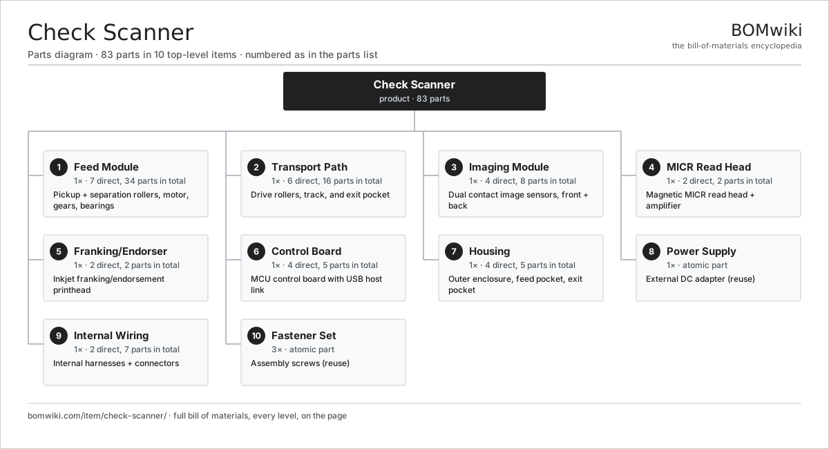
| # | Part | Qty | What it does |
|---|---|---|---|
| 1 | Feed Module 7 parts | 1× | Pickup + separation rollers, motor, gears, bearings |
| 2 | Transport Path 6 parts | 1× | Drive rollers, track, and exit pocket |
| 3 | Imaging Module 4 parts | 1× | Dual contact image sensors, front + back |
| 4 | MICR Read Head 2 parts | 1× | Magnetic MICR read head + amplifier |
| 5 | Franking/Endorser 2 parts | 1× | Inkjet franking/endorsement printhead |
| 6 | Control Board 4 parts | 1× | MCU control board with USB host link |
| 7 | Housing 4 parts | 1× | Outer enclosure, feed pocket, exit pocket |
| 8 | Power Supply | 1× | External DC adapter (reuse) |
| 9 | Internal Wiring 2 parts | 1× | Internal harnesses + connectors |
| 10 | Fastener Set | 3× | Assembly screws (reuse) |
3D model
No 3D model yet. Have a CAD file of this? Add a 3D model. STL renders right on this page; STEP, FreeCAD, and OpenSCAD sources are welcome too (openly licensed, like all 3D models on BOMwiki).
Build & assembly graph
expand / collapse · shared sub-assemblies converge · links to related products · est. labourTap an assembly to expand/collapse · tap a part to open it · use “Open page” for any node · drag to pan, scroll to zoom.
Bill of materials for Check Scanner
10 top-level lines · 44 rows shown · 83 parts total · indented to 3 levels| # | Item / sub-assembly | Part no. | Qty/assy | Ext. qty | Parts | Type |
|---|---|---|---|---|---|---|
| 1 | Feed Module 7 parts | check-scanner-feed-module | 1× | 1 | 34 | assembly |
| 1.1 | Pickup Roller | check-scanner-pickup-roller | 1× | 1 | · | part |
| 1.2 | Separation Roller | check-scanner-separation-roller | 1× | 1 | · | part |
| 1.3 | Separation Pad | check-scanner-separation-pad | 1× | 1 | · | part |
| 1.4 | Feed Motor 3 parts | check-scanner-feed-motor | 1× | 1 | 24 | assembly |
| 1.4.1 | Stator Assembly 3 parts + deeper › | stator-assembly | 1× | 1 | 3 | assembly |
| 1.4.2 | Rotor Assembly 4 parts + deeper › | rotor-assembly | 1× | 1 | 19 | assembly |
| 1.4.3 | Ball Bearing | ball-bearing | 2× | 2 | · | part |
| 1.5 | Helical Gear Pair | gear-pair | 2× | 2 | · | part |
| 1.6 | Ball Bearing | ball-bearing | 4× | 4 | · | part |
| 1.7 | Feed Sensor | check-scanner-feed-sensor | 1× | 1 | · | part |
| 2 | Transport Path 6 parts | check-scanner-transport | 1× | 1 | 16 | assembly |
| 2.1 | Drive Roller | check-scanner-drive-roller | 3× | 3 | · | part |
| 2.2 | Pinch Roller | check-scanner-pinch-roller | 3× | 3 | · | part |
| 2.3 | Guide Track | check-scanner-track | 1× | 1 | · | part |
| 2.4 | Exit Pocket | check-scanner-exit-pocket | 1× | 1 | · | part |
| 2.5 | Ball Bearing | ball-bearing | 6× | 6 | · | part |
| 2.6 | Track Sensor | check-scanner-track-sensor | 2× | 2 | · | part |
| 3 | Imaging Module 4 parts | check-scanner-imaging | 1× | 1 | 8 | assembly |
| 3.1 | CMOS Image Sensor | image-sensor | 2× | 2 | · | part |
| 3.2 | CIS Illumination Bar | check-scanner-cis-illumination | 2× | 2 | · | part |
| 3.3 | Rod-Lens Array | check-scanner-lens-array | 2× | 2 | · | part |
| 3.4 | Scan Glass | check-scanner-scan-glass | 2× | 2 | · | part |
| 4 | MICR Read Head 2 parts | check-scanner-micr-head | 1× | 1 | 2 | assembly |
| 4.1 | Magnetic Pickup Head | check-scanner-magnetic-head | 1× | 1 | · | part |
| 4.2 | MICR Amplifier Board | check-scanner-micr-amp | 1× | 1 | · | part |
| 5 | Franking/Endorser 2 parts | check-scanner-endorser | 1× | 1 | 2 | assembly |
| 5.1 | Inkjet Printhead | check-scanner-inkjet-head | 1× | 1 | · | part |
| 5.2 | Ink Cartridge | check-scanner-ink-cartridge | 1× | 1 | · | part |
| 6 | Control Board 4 parts | check-scanner-control-board | 1× | 1 | 5 | assembly |
| 6.1 | Bare PCB | pcb-bare | 1× | 1 | · | part |
| 6.2 | Microcontroller | mcu | 1× | 1 | · | part |
| 6.3 | SMD Passive (R/C/L) | smd-passives | 1× | 1 | · | part |
| 6.4 | Connector | connector | 2× | 2 | · | part |
| 7 | Housing 4 parts | check-scanner-housing | 1× | 1 | 5 | assembly |
| 7.1 | Top Cover | check-scanner-top-cover | 1× | 1 | · | part |
| 7.2 | Base Chassis | check-scanner-base | 1× | 1 | · | part |
| 7.3 | Feed Pocket | check-scanner-feed-pocket | 1× | 1 | · | part |
| 7.4 | Fastener Set | fastener-set | 2× | 2 | · | part |
| 8 | Power Supply | power-supply | 1× | 1 | · | part |
| 9 | Internal Wiring 2 parts | check-scanner-wiring | 1× | 1 | 7 | assembly |
| 9.1 | Wire Bundle | wire-bundle | 2× | 2 | · | part |
| 9.2 | Connector | connector | 5× | 5 | · | part |
| 10 | Fastener Set | fastener-set | 3× | 3 | · | part |
Something wrong in this list? Report a problem with this BOM.
Related products
same domain, ranked by shared parts Photocopier (MFP)
210 parts · shares 14 with this page
 Document Scanner
79 parts · shares 13 with this page
 Money Counting Machine
102 parts · shares 13 with this page
Automatic Letter Opener
58 parts · shares 13 with this page
Coin Sorter / Counter
95 parts · shares 13 with this page
 Folding & Inserting Machine
151 parts · shares 13 with this page
Sourcing: possible vendors
Browse the supplier directory → Prices, MOQ, and lead times are algorithmic estimates, not quotes, and not claims about these companies. Company mappings are curated by keyword; est. price band $50–$15k. How estimates work| Vendor | HQ | Specialty | MOQ | Lead time |
|---|---|---|---|---|
|
🇯🇵Canon
canon.com ↗
|
Tokyo, JP | Imaging & optics | 500 units | 8–12 wks |
|
🇯🇵Ricoh
ricoh.com ↗
|
Tokyo, JP | Office imaging | 500 units | 8–12 wks |
|
🇺🇸Xerox
xerox.com ↗
|
Norwalk, US | Printers & copiers | 500 units | 8–12 wks |
|
🇯🇵Epson
epson.com ↗
|
Suwa, JP | Printers & projectors | 500 units | 8–12 wks |
|
🇯🇵Brother
brother.com ↗
|
Nagoya, JP | Printers & sewing | 500 units | 8–12 wks |
402-word article