Industrial Ethernet Switch
ProductOverview
An industrial Ethernet switch does the same forwarding job as an office switch, but it has to survive a factory floor, a trackside cabinet, or an electrical substation: wide temperature swings, vibration, dust, and the electrical surges that come with heavy machinery nearby. It is fanless to avoid a moving part that would clog or fail, mounts on a DIN rail beside the PLCs and drives it serves, and takes redundant DC power so a single feed failure does not bring the network segment down. Ring-redundancy protocols let it recover from a broken link in milliseconds, which matters when the traffic is real-time control rather than email.
How it works
Field cabling lands on the Port Module. Each copper port uses a metal-shelled Shielded RJ45 Jack and an extended-temperature Ethernet Magnetics module for isolation, driven by an Ethernet PHY, while the SFP Cage slots accept fiber transceivers for long runs immune to ground-potential differences. Frames reach the Switch Mainboard, where the Compute SoC Module switch fabric forwards them and the Microcontroller handles management, ring protocols, and the alarm logic. Every line is guarded by an Surge Protector network that clamps the transients which would otherwise destroy the PHYs.
Power comes in on the Power Input Stage stage: two DC feeds are combined through ORing Diode ORing devices so either can fail without interrupting the rails, and an Alarm Relay changes state on a fault to signal a control room. Field wiring is landed on the pluggable Terminal Block.
Because the boards run in humid, dusty, sometimes corrosive air, they are sealed with Conformal Coating and housed in the finned DIN-Rail Housing, which sheds heat by convection alone. The Front Panel Indicators reports power, alarm, and per-port link state.
Industrial Ethernet Switch parts and their functions
7 top-level parts · 508 parts in total · full bill of materials below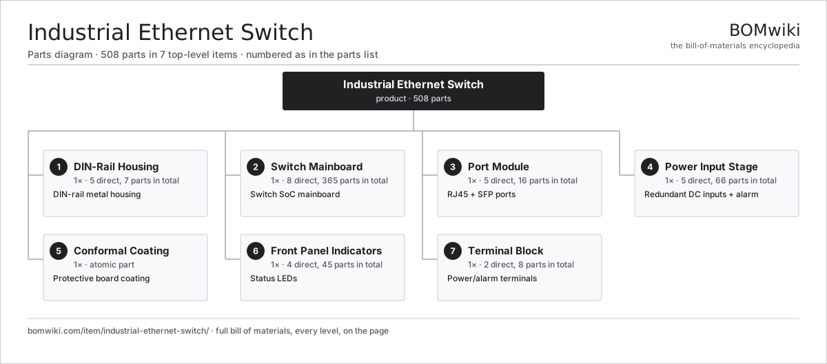
| # | Part | Qty | What it does |
|---|---|---|---|
| 1 | DIN-Rail Housing 5 parts | 1× | DIN-rail metal housing |
| 2 | Switch Mainboard 8 parts | 1× | Switch SoC mainboard |
| 3 | Port Module 5 parts | 1× | RJ45 + SFP ports |
| 4 | Power Input Stage 5 parts | 1× | Redundant DC inputs + alarm |
| 5 | Conformal Coating | 1× | Protective board coating |
| 6 | Front Panel Indicators 4 parts | 1× | Status LEDs |
| 7 | Terminal Block 2 parts | 1× | Power/alarm terminals |
3D model
No 3D model yet. Have a CAD file of this? Add a 3D model. STL renders right on this page; STEP, FreeCAD, and OpenSCAD sources are welcome too (openly licensed, like all 3D models on BOMwiki).
Build & assembly graph
expand / collapse · shared sub-assemblies converge · links to related products · est. labourTap an assembly to expand/collapse · tap a part to open it · use “Open page” for any node · drag to pan, scroll to zoom.
Bill of materials for Industrial Ethernet Switch
7 top-level lines · 36 rows shown · 508 parts total · indented to 3 levels| # | Item / sub-assembly | Part no. | Qty/assy | Ext. qty | Parts | Type |
|---|---|---|---|---|---|---|
| 1 | DIN-Rail Housing 5 parts | ies-housing | 1× | 1 | 7 | assembly |
| 1.1 | Sheet Metal Panel | sheet-panel | 3× | 3 | · | part |
| 1.2 | DIN-Rail Clip | ies-din-clip | 1× | 1 | · | part |
| 1.3 | Heat Fin | ies-heat-fin | 1× | 1 | · | part |
| 1.4 | Sealing Gasket | ies-gasket | 1× | 1 | · | part |
| 1.5 | Fastener Set | fastener-set | 1× | 1 | · | part |
| 2 | Switch Mainboard 8 parts | ies-mainboard | 1× | 1 | 365 | assembly |
| 2.1 | Bare PCB | pcb-bare | 1× | 1 | · | part |
| 2.2 | Compute SoC Module | soc-module | 1× | 1 | · | part |
| 2.3 | Microcontroller | mcu | 1× | 1 | · | part |
| 2.4 | Firmware Flash | ies-flash | 1× | 1 | · | part |
| 2.5 | Surge Protector | ies-surge-protector | 8× | 8 | · | part |
| 2.6 | DC-DC Converter | ies-dc-dc | 2× | 2 | · | part |
| 2.7 | Clock Oscillator | ies-clock-osc | 1× | 1 | · | part |
| 2.8 | SMD Passive (R/C/L) | smd-passives | 350× | 350 | · | part |
| 3 | Port Module 5 parts | ies-port-module | 1× | 1 | 16 | assembly |
| 3.1 | Shielded RJ45 Jack | ies-rj45-jack | 8× | 8 | · | part |
| 3.2 | Ethernet Magnetics | ies-magnetics | 2× | 2 | · | part |
| 3.3 | Ethernet PHY | ies-ethernet-phy | 2× | 2 | · | part |
| 3.4 | SFP Cage | ies-sfp-cage | 2× | 2 | · | part |
| 3.5 | Connector | connector | 2× | 2 | · | part |
| 4 | Power Input Stage 5 parts | ies-power-input | 1× | 1 | 66 | assembly |
| 4.1 | Bare PCB | pcb-bare | 1× | 1 | · | part |
| 4.2 | ORing Diode | ies-input-diode | 2× | 2 | · | part |
| 4.3 | EMI Input Filter | ies-input-filter | 2× | 2 | · | part |
| 4.4 | Alarm Relay | ies-alarm-relay | 1× | 1 | · | part |
| 4.5 | SMD Passive (R/C/L) | smd-passives | 60× | 60 | · | part |
| 5 | Conformal Coating | ies-conformal-coating | 1× | 1 | · | part |
| 6 | Front Panel Indicators 4 parts | ies-front-panel | 1× | 1 | 45 | assembly |
| 6.1 | Bare PCB | pcb-bare | 1× | 1 | · | part |
| 6.2 | Status LED | ies-status-led | 4× | 4 | · | part |
| 6.3 | Port LED | ies-port-led | 10× | 10 | · | part |
| 6.4 | SMD Passive (R/C/L) | smd-passives | 30× | 30 | · | part |
| 7 | Terminal Block 2 parts | ies-terminal-block | 1× | 1 | 8 | assembly |
| 7.1 | Connector | connector | 2× | 2 | · | part |
| 7.2 | Terminal Screw | ies-terminal-screw | 6× | 6 | · | part |
Something wrong in this list? Report a problem with this BOM.
Related products
same domain, ranked by shared parts 5G Base Station
436 parts · shares 4 with this page
Data Center Switch (Spine)
3,264 parts · shares 4 with this page
 Firewall Appliance
82 parts · shares 4 with this page
Load Balancer Appliance
911 parts · shares 4 with this page
 Network Switch
1,367 parts · shares 4 with this page
 Satellite Modem
807 parts · shares 4 with this page
Sourcing: possible vendors
Browse the supplier directory → Prices, MOQ, and lead times are algorithmic estimates, not quotes, and not claims about these companies. Company mappings are curated by keyword; est. price band $30–$50k. How estimates work| Vendor | HQ | Specialty | MOQ | Lead time |
|---|---|---|---|---|
|
🇺🇸Cisco
cisco.com ↗
|
San Jose, US | Networking | 500 units | 8–14 wks |
|
🇺🇸Juniper
juniper.net ↗
|
Sunnyvale, US | Networking | 500 units | 8–14 wks |
| arista.com ↗ | Santa Clara, US | Networking | 500 units | 8–14 wks |
|
🇫🇮Nokia
nokia.com ↗
|
Espoo, FI | Telecom equipment | 500 units | 8–14 wks |
|
🇨🇳Huawei
huawei.com ↗
|
Shenzhen, CN | Networking & telecom | 500 units | 8–14 wks |
302-word article