Industrial Helical Gearbox
ProductOverview
Industrial helical gearboxes are compact speed reducers used in machinery ranging from conveyor drives to printing presses. They employ angled (helical) gear teeth that mesh diagonally across the gear face, distributing load over multiple teeth simultaneously. This geometry provides smoother, quieter operation than spur gears and enables efficient power transmission across rigid parallel shafts.
Modern helical gearboxes typically combine two or three gear stages housed in ductile iron or aluminum castings. The 3:1 to 25:1 ratio range covers most industrial fan and pump drives. Efficiency commonly reaches 92–94% per stage due to the helical geometry and precision bearing support, making them ideal for continuous-duty machines in textile mills, food processing, and chemical plants.
How it works
Input torque enters through the input shaft, rotating at motor speed (500–3600 RPM). The first-stage pinion drives a larger helical wheel, reducing speed while multiplying torque. The wheel is locked to an intermediate shaft that feeds the second-stage pinion, which in turn drives the output wheel and flange-coupled load.
The helical angle (typically 15–25°) creates an axial thrust component that the bearing cartridge must resist. Angular-contact bearings are preloaded with disc springs to maintain stiffness under variable load. Oil lubrication is drawn by rotation across the gear mesh and cascades down to the sump for continuous recirculation, dissipating frictional heat and preventing metal fatigue.
Design features
The housing is a rigid casting that encloses the gear mesh and contains leakage. Split at the centerline, it allows field disassembly for maintenance without removing input and output shafts. End plates secured by socket-head cap screws locate the bearing journals and provide a barrier against external moisture and contaminants.
The seal system uses dual lip seals at input and output shafts, backed by static gaskets at the housing split line. A small breather allows internal pressure to equalize with atmosphere while a silica-gel element blocks humidity. This dual defense prevents oil weeping and extends bearing life in humid or dusty environments.
Load and lifespan
Helical gearboxes are rated at nominal input power and speed, with safety factors applied to account for service class (continuous vs. intermittent) and duty cycle (fan, pump, crusher). Design life typically assumes 10,000–20,000 operating hours before bearing fatigue; modern sealed designs with synthetic oil extend this to 30,000+ hours in clean environments.
Failure modes include tooth pitting (micropitting), micropitting progression to macropitting, bearing spalling, and seal leakage. Root cause analysis typically points to insufficient lubrication (starvation, oxidation), misalignment (shaft runout >0.05 mm), or bearing preload drift. Quarterly drain analysis and filter inspection are standard predictive maintenance practices in food and chemical plants.
Standards and variants
ISO 841 defines the mechanical power transmission interface (flange couplings, foot dimensions). Helical gearboxes are manufactured in metric and imperial versions, with DIN, AGMA, and ISO rating standards. Sealed and open-bath versions exist; sealed designs use synthetic oils (PAG, PAO) for longer change intervals and are preferred in food, dairy, and beverage filling lines to prevent mineral oil carryover.
In wind energy, helical-helical three-stage gearboxes step 10–15 RPM rotor speed up to 1200+ RPM generator input. Industrial process heating and cooling loops favor sealed helical units with thermostatic control of outlet oil temperature, cooling jackets or heat exchangers manage dissipation in high-duty factories.
Industrial Helical Gearbox parts and their functions
7 top-level parts · 36 parts in total · full bill of materials below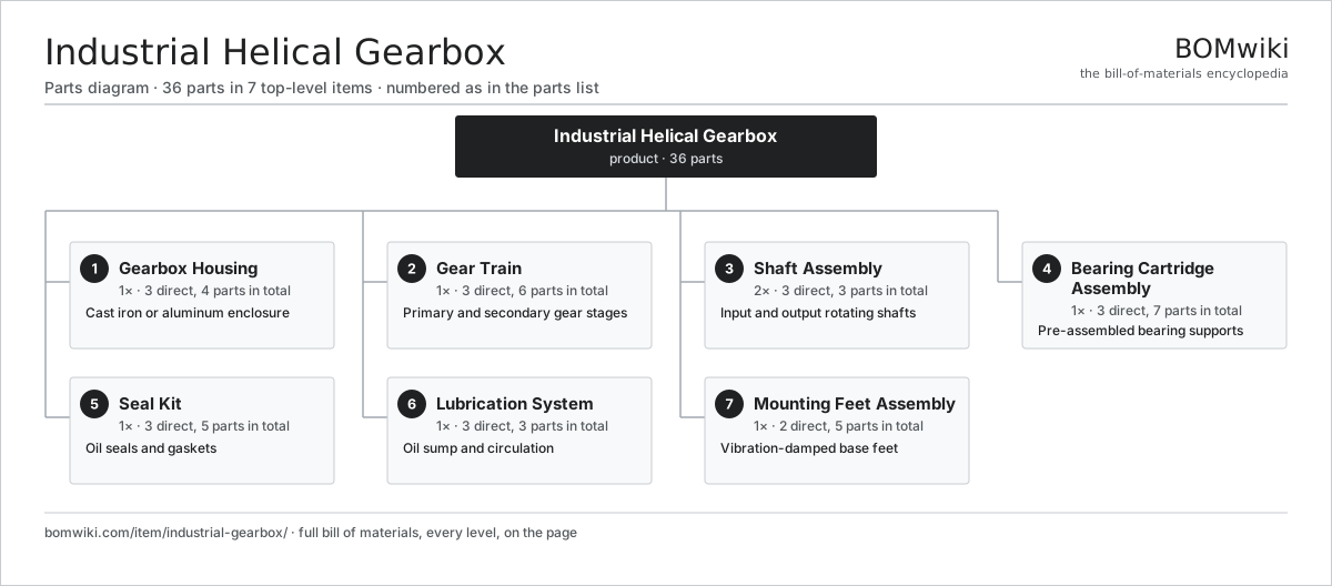
| # | Part | Qty | What it does |
|---|---|---|---|
| 1 | Gearbox Housing 3 parts | 1× | Cast iron or aluminum enclosure |
| 2 | Gear Train 3 parts | 1× | Primary and secondary gear stages |
| 3 | Shaft Assembly 3 parts | 2× | Input and output rotating shafts |
| 4 | Bearing Cartridge Assembly 3 parts | 1× | Pre-assembled bearing supports |
| 5 | Seal Kit 3 parts | 1× | Oil seals and gaskets |
| 6 | Lubrication System 3 parts | 1× | Oil sump and circulation |
| 7 | Mounting Feet Assembly 2 parts | 1× | Vibration-damped base feet |
3D model
No 3D model yet. Have a CAD file of this? Add a 3D model. STL renders right on this page; STEP, FreeCAD, and OpenSCAD sources are welcome too (openly licensed, like all 3D models on BOMwiki).
Build & assembly graph
expand / collapse · shared sub-assemblies converge · links to related products · est. labourTap an assembly to expand/collapse · tap a part to open it · use “Open page” for any node · drag to pan, scroll to zoom.
Bill of materials for Industrial Helical Gearbox
7 top-level lines · 27 rows shown · 36 parts total · indented to 3 levels| # | Item / sub-assembly | Part no. | Qty/assy | Ext. qty | Parts | Type |
|---|---|---|---|---|---|---|
| 1 | Gearbox Housing 3 parts | industrial-gearbox-housing | 1× | 1 | 4 | assembly |
| 1.1 | Gearbox Housing | gearbox-housing | 1× | 1 | · | part |
| 1.2 | End Plate Assembly | industrial-gearbox-end-plate | 2× | 2 | · | part |
| 1.3 | Fastener Set | fastener-set | 1× | 1 | · | part |
| 2 | Gear Train 3 parts | industrial-gearbox-gear-train | 1× | 1 | 6 | assembly |
| 2.1 | Helical Gear Pair | gear-pair | 2× | 2 | · | part |
| 2.2 | Helical Pinion | industrial-gearbox-pinion | 2× | 2 | · | part |
| 2.3 | Helical Wheel | industrial-gearbox-wheel | 2× | 2 | · | part |
| 3 | Shaft Assembly 3 parts | industrial-gearbox-shaft-assembly | 2× | 2 | 3 | assembly |
| 3.1 | Steel Shaft | industrial-gearbox-shaft | 1× | 2 | · | part |
| 3.2 | Shaft Key | industrial-gearbox-shaft-key | 1× | 2 | · | part |
| 3.3 | Fastener Set | fastener-set | 1× | 2 | · | part |
| 4 | Bearing Cartridge Assembly 3 parts | industrial-gearbox-bearing-cartridge | 1× | 1 | 7 | assembly |
| 4.1 | Ball Bearing | ball-bearing | 4× | 4 | · | part |
| 4.2 | Bearing Collar | industrial-gearbox-bearing-collar | 2× | 2 | · | part |
| 4.3 | Preload Spring | industrial-gearbox-preload-spring | 1× | 1 | · | part |
| 5 | Seal Kit 3 parts | industrial-gearbox-seal-kit | 1× | 1 | 5 | assembly |
| 5.1 | Oil Seal | oil-seal | 2× | 2 | · | part |
| 5.2 | Housing Gasket | industrial-gearbox-gasket | 2× | 2 | · | part |
| 5.3 | O-Ring Set | oring-set | 1× | 1 | · | part |
| 6 | Lubrication System 3 parts | industrial-gearbox-lube-system | 1× | 1 | 3 | assembly |
| 6.1 | Oil Sump | industrial-gearbox-sump | 1× | 1 | · | part |
| 6.2 | Drain Plug | industrial-gearbox-drain-plug | 1× | 1 | · | part |
| 6.3 | Breather Element | industrial-gearbox-breather | 1× | 1 | · | part |
| 7 | Mounting Feet Assembly 2 parts | industrial-gearbox-mounting-feet | 1× | 1 | 5 | assembly |
| 7.1 | Elastomer Foot | industrial-gearbox-foot | 4× | 4 | · | part |
| 7.2 | Fastener Set | fastener-set | 1× | 1 | · | part |
Something wrong in this list? Report a problem with this BOM.
Related products
same domain, ranked by shared parts Continuous Galvanizing Line
1,296 parts · shares 5 with this page
 Decanter Centrifuge
172 parts · shares 5 with this page
 Foundry Sand Mixer
93 parts · shares 5 with this page
Sourcing: possible vendors
Browse the supplier directory → Prices, MOQ, and lead times are algorithmic estimates, not quotes, and not claims about these companies. Company mappings are curated by keyword; est. price band $5k–$2M. How estimates work| Vendor | HQ | Specialty | MOQ | Lead time |
|---|---|---|---|---|
| atlascopco.com ↗ | Stockholm, SE | Compressors & industrial | 10 units | 12–20 wks |
|
🇦🇹Andritz
andritz.com ↗
|
Graz, AT | Process plants & machinery | 10 units | 12–20 wks |
| buhlergroup.com ↗ | Uzwil, CH | Food & materials processing | 10 units | 12–20 wks |
| gea.com ↗ | Düsseldorf, DE | Process technology | 10 units | 12–20 wks |
| mhi.com ↗ | Tokyo, JP | Heavy machinery | 10 units | 12–20 wks |
590-word article