Smart Irrigation Controller
ProductOverview
A smart irrigation controller is the timer at the head of a sprinkler system, upgraded with a network connection and sensor inputs so that watering tracks actual conditions instead of a fixed calendar. The electrical contract it serves is decades old and entirely standard: each irrigation zone is a 24 VAC solenoid valve buried in a valve box, wired back to the controller with a shared common wire. Energise a zone wire and that valve opens; remove power and it closes. Everything the product does reduces to deciding when to energise which output on the Zone Output Stage stage.
The "smart" layer earns its name through water savings. A fixed timer waters through rainstorms and waters identically in April and August. Connected controllers that adjust run times from weather data (evapotranspiration, or ET, scheduling) typically cut outdoor water use by 20–30%, which is why utility rebate programmes and the US EPA WaterSense certification exist for this category.
How it works
The Main Controller Board runs the schedule. An Microcontroller holds the zone programmes, up to four independent programmes with six start times each, in EEPROM, and a battery-backed Real-Time Clock keeps real time through outages so a power blip does not shift watering into the afternoon. The Compute SoC Module handles 802.11 WiFi through a PCB trace WiFi Antenna; through it the controller fetches weather forecasts and ET estimates, and exposes the app interface used for remote control.
When a start time arrives, the MCU fires one Zone Triac through an optical trigger, switching 24 VAC onto that zone's terminal at the Terminal Block. A Relay closes in parallel to drive a master valve or a pump-start contactor, common on systems fed from a well or lake rather than mains pressure. Zones run one at a time because the plug-in transformer and the hydraulics are both sized for a single valve's flow.
The Current Sense Circuit circuit watches solenoid current on the active output. A reading near zero means a broken wire or failed coil; a reading far above 300 mA means a shorted solenoid that would eventually cook the transformer. Either condition is logged, the zone is skipped, and the fault Status LED and app are notified, wiring faults in buried runs are the dominant failure mode of installed systems.
Sensors and weather logic
Three local inputs complement the cloud weather feed through the Sensor Interface, each isolated by an Optocoupler because sensor wires run outdoors and pick up surges.
The Rain Sensor is the simplest and most mandated device (several US states require one): hygroscopic discs swell after measurable rain and hold a switch open, vetoing all watering until they dry out at roughly the rate soil does. The Soil Moisture Probe reports volumetric water content from the root zone, letting the controller skip cycles while moisture is above a set threshold rather than estimating from weather. The Flow Meter Input counts pulses from an inline turbine meter; flow far above the zone's learned baseline indicates a broken head or lateral pipe, and the controller closes the master valve rather than empty a few thousand litres onto the lawn.
Power and protection
Power arrives from the standard 24 VAC wall transformer (Power Supply) used across the irrigation industry, protected by a Thermal Fuse. The Bridge Rectifier produces an unregulated DC rail, and an Buck Converter steps it to 3.3 V for logic and radio. Valve outputs stay AC because solenoid valves are AC devices, the impedance of the energised coil limits holding current, and AC avoids the DC electrolytic corrosion that would otherwise attack splices in wet valve boxes.
Lightning is the environmental threat that shapes the output stage. Valve wires act as long buried antennas for nearby strikes, so every field terminal carries a metal-oxide Surge Suppressor clamping transients before they reach the triacs.
Packaging and local control
The electronics mount in a polycarbonate enclosure: the Case Back carries keyhole wall mounts and knockouts, field cable enters through Cable Glands, and the gasketed Case Door brings the assembly to IP44 for garage or sheltered outdoor walls.
The Front Panel exists because irrigation is maintained by people standing at the valve box, often without the homeowner's phone: an LCD Panel and Keypad allow manual zone runs for head flushing and winterisation blow-outs, a rain delay button, and full programme editing. The controller is fully functional with WiFi down, the cloud adjusts schedules, but the schedule itself always lives locally in EEPROM and executes from the RTC.
Smart Irrigation Controller parts and their functions
6 top-level parts · 53 parts in total · full bill of materials below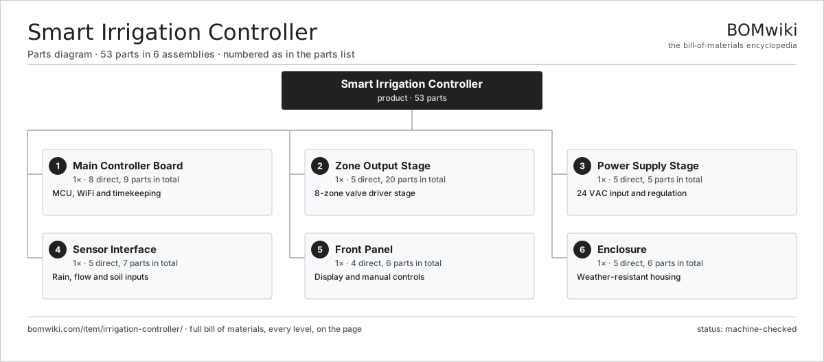
| # | Part | Qty | What it does |
|---|---|---|---|
| 1 | Main Controller Board 8 parts | 1× | MCU, WiFi and timekeeping |
| 2 | Zone Output Stage 5 parts | 1× | 8-zone valve driver stage |
| 3 | Power Supply Stage 5 parts | 1× | 24 VAC input and regulation |
| 4 | Sensor Interface 5 parts | 1× | Rain, flow and soil inputs |
| 5 | Front Panel 4 parts | 1× | Display and manual controls |
| 6 | Enclosure 5 parts | 1× | Weather-resistant housing |
3D model
No 3D model yet. Have a CAD file of this? Add a 3D model. STL renders right on this page; STEP, FreeCAD, and OpenSCAD sources are welcome too (openly licensed, like all 3D models on BOMwiki).
Build & assembly graph
expand / collapse · shared sub-assemblies converge · links to related products · est. labourTap an assembly to expand/collapse · tap a part to open it · use “Open page” for any node · drag to pan, scroll to zoom.
Bill of materials for Smart Irrigation Controller
6 top-level lines · 38 rows shown · 53 parts total · indented to 3 levels| # | Item / sub-assembly | Part no. | Qty/assy | Ext. qty | Parts | Type |
|---|---|---|---|---|---|---|
| 1 | Main Controller Board 8 parts | irrigation-controller-main-board | 1× | 1 | 9 | assembly |
| 1.1 | Bare PCB | pcb-bare | 1× | 1 | · | part |
| 1.2 | Microcontroller | mcu | 1× | 1 | · | part |
| 1.3 | Compute SoC Module | soc-module | 1× | 1 | · | part |
| 1.4 | Real-Time Clock | irrigation-controller-rtc | 1× | 1 | · | part |
| 1.5 | EEPROM | irrigation-controller-eeprom | 1× | 1 | · | part |
| 1.6 | WiFi Antenna | irrigation-controller-antenna | 1× | 1 | · | part |
| 1.7 | SMD Passive (R/C/L) | smd-passives | 1× | 1 | · | part |
| 1.8 | Connector | connector | 2× | 2 | · | part |
| 2 | Zone Output Stage 5 parts | irrigation-controller-zone-outputs | 1× | 1 | 20 | assembly |
| 2.1 | Zone Triac | irrigation-controller-triac | 8× | 8 | · | part |
| 2.2 | Relay | relay | 1× | 1 | · | part |
| 2.3 | Surge Suppressor | irrigation-controller-surge-suppressor | 9× | 9 | · | part |
| 2.4 | Terminal Block | irrigation-controller-terminal-block | 1× | 1 | · | part |
| 2.5 | Current Sense Circuit | irrigation-controller-current-sense | 1× | 1 | · | part |
| 3 | Power Supply Stage 5 parts | irrigation-controller-power | 1× | 1 | 5 | assembly |
| 3.1 | Power Supply | power-supply | 1× | 1 | · | part |
| 3.2 | Bridge Rectifier | irrigation-controller-rectifier | 1× | 1 | · | part |
| 3.3 | Buck Converter | irrigation-controller-buck-converter | 1× | 1 | · | part |
| 3.4 | Thermal Fuse | thermal-fuse | 1× | 1 | · | part |
| 3.5 | Connector | connector | 1× | 1 | · | part |
| 4 | Sensor Interface 5 parts | irrigation-controller-sensor-interface | 1× | 1 | 7 | assembly |
| 4.1 | Rain Sensor | irrigation-controller-rain-sensor | 1× | 1 | · | part |
| 4.2 | Soil Moisture Probe | irrigation-controller-soil-probe | 1× | 1 | · | part |
| 4.3 | Flow Meter Input | irrigation-controller-flow-input | 1× | 1 | · | part |
| 4.4 | Optocoupler | irrigation-controller-optocoupler | 3× | 3 | · | part |
| 4.5 | SMD Passive (R/C/L) | smd-passives | 1× | 1 | · | part |
| 5 | Front Panel 4 parts | irrigation-controller-front-panel | 1× | 1 | 6 | assembly |
| 5.1 | LCD Panel | lcd-panel | 1× | 1 | · | part |
| 5.2 | Keypad | irrigation-controller-keypad | 1× | 1 | · | part |
| 5.3 | Status LED | irrigation-controller-status-led | 3× | 3 | · | part |
| 5.4 | Front Bezel | irrigation-controller-front-bezel | 1× | 1 | · | part |
| 6 | Enclosure 5 parts | irrigation-controller-enclosure | 1× | 1 | 6 | assembly |
| 6.1 | Case Back | irrigation-controller-case-back | 1× | 1 | · | part |
| 6.2 | Case Door | irrigation-controller-case-door | 1× | 1 | · | part |
| 6.3 | Cable Gland | irrigation-controller-cable-gland | 2× | 2 | · | part |
| 6.4 | O-Ring Set | oring-set | 1× | 1 | · | part |
| 6.5 | Fastener Set | fastener-set | 1× | 1 | · | part |
Something wrong in this list? Report a problem with this BOM.
Related products
same domain, ranked by shared parts Soil Steam Sterilizer
83 parts · shares 8 with this page
 Robotic Lawn Mower
136 parts · shares 6 with this page
 Electric Fence Energizer
37 parts · shares 6 with this page
 Greenhouse Heater
50 parts · shares 4 with this page
 Pop-Up Sprinkler System
135 parts · shares 4 with this page
Greenhouse Exhaust Fan
70 parts · shares 2 with this page
Sourcing: possible vendors
Browse the supplier directory → Prices, MOQ, and lead times are algorithmic estimates, not quotes, and not claims about these companies. Company mappings are curated by keyword; est. price band $80–$5k. How estimates work| Vendor | HQ | Specialty | MOQ | Lead time |
|---|---|---|---|---|
| husqvarna.com ↗ | Stockholm, SE | Outdoor power products | 500 units | 8–14 wks |
|
🇩🇪STIHL
stihl.com ↗
|
Waiblingen, DE | Chainsaws & outdoor power | 500 units | 8–14 wks |
|
🇺🇸Toro
thetorocompany.com ↗
|
Bloomington, US | Turf & outdoor equipment | 500 units | 8–14 wks |
| powerequipment.honda.com ↗ | Tokyo, JP | Engines & outdoor power | 500 units | 8–14 wks |
|
🇨🇳Chervon
chervongroup.com ↗
|
Nanjing, CN | Power tools (EGO, SKIL) | 500 units | 8–14 wks |
796-word article