Lavatory Service Truck
ProductAlso known as: Aircraft Lavatory Service Truck
Overview
An aircraft lavatory service truck services the waste and fresh-water systems of commercial aircraft parked at airport gates, pumping out accumulated human waste and refilling the fresh-water supply for toilet flushing. Operating at major commercial airports worldwide, the truck combines vacuum extraction and pressurized water supply into a single mobile utility platform.
The foundation is a medium-duty commercial truck chassis: a 2.0–3.0 L turbocharged diesel producing 80–120 hp, paired with a five-speed automatic transmission. The payload capacity is 4000 kg, reflecting the combined weight of two tanks (waste and water) at maximum fill.
The core components are two large tanks: a waste tank (2500 L stainless steel 304) and a fresh-water tank (1500 L food-grade stainless steel). The waste tank is sealed and equipped with baffle plates to prevent sloshing during transport. A vacuum pump (rotary vane, −0.8 bar capacity) draws waste from aircraft lavatories through a 50 m suction hose at rates up to 200 L/min, accumulating solid waste and urine in the tank. A level sensor (capacitive) continuously monitors tank fill; when approaching 90% capacity, the operator must return to the airport service facility for emptying.
The fresh-water tank is pressurized to 2 bar by a separate pressurization tank, allowing gravity-fed water to flow to aircraft lavatories through a 40 m delivery hose. A positive-displacement gear pump (50 L/min @ 5 bar) can actively refill the tank at aircraft service points; an inline one-way check valve prevents backflow from aircraft to truck if aircraft pressure exceeds truck pressure.
A 10 hp three-phase electric motor (480 V supply) drives both pumps via a solenoid-controlled directional valve: when the operator selects waste extraction mode, the motor drives the vacuum pump; in fresh-water refill mode, the motor drives the gear pump. This dual-pump configuration eliminates the need for two separate motors.
Two motorized hose reels hold the suction and water hoses, with automatic retraction and locking mechanisms. The waste hose is conductive rubber (preventing electrostatic buildup), while the water hose is food-grade rubber (preventing chemical contamination of potable water).
The operator's control panel features a two-position pump switch (off/on), a mode selector switch (waste extraction vs. water supply), and analog gauges displaying waste tank level, water tank level, and water supply pressure. An emergency stop button cuts all electrical power instantly.
Quick-disconnect couplers matching aircraft service ports allow rapid connection and disconnection, minimizing gate turnaround time. A ground cable bonds the truck to the aircraft, discharging electrostatic charge safely.
How it works
An aircraft arrives at a gate after a flight. Flight attendants have emptied portable lavatories (smaller aircraft) or the lavatory waste tank needs servicing (larger aircraft). The airport's ramp service coordinator dispatches a lavatory service truck.
The truck driver positions the vehicle alongside the aircraft, typically 3–5 m away, maneuvering the truck to align the hose reels with the aircraft's service ports (typically located on the belly, forward and aft of the main landing gear). The driver engages the automatic hose reel motors: the waste suction hose extends from its reel over the truck body via pulleys and routing guides, reaching the aircraft's waste service port. Similarly, the fresh-water delivery hose extends from its reel to the aircraft's fresh-water inlet port.
The driver connects the quick-disconnect Waste Suction Coupler to the aircraft waste port and the Water Supply Coupler to the fresh-water inlet. A ground cable is connected from the truck chassis to the aircraft fuselage, bonding them electrically to prevent electrostatic discharge during pumping.
The driver then returns to the truck cab and monitors the Waste Tank Level Gauge and Water Tank Level Gauge. If the waste tank is below 90% capacity, the driver selects the waste extraction mode via the Mode Selector Switch, engages the Pump On/Off Switch to start the motor, and the vacuum pump begins extracting waste from the aircraft.
The Vacuum Pump creates a −0.8 bar vacuum, drawing waste through the 50 mm suction hose at ~200 L/min. The waste passes through the hose and into the Waste Tank Assembly, where baffle plates slow the flow, allowing solids to settle. The vacuum pump runs for 2–5 minutes until the waste tank level reaches ~90% (confirmed by the Level Sensor).
The driver then switches to fresh-water refill mode. If the water tank is already at 100% capacity (pre-filled at the service facility), the driver can simply dispense water to the aircraft's tank. The Gear Pump pressurizes the fresh-water tank to 5 bar, forcing water through the 38 mm delivery hose into the aircraft's fresh-water inlet. The Water Pressure Gauge displays delivery pressure; a typical refill takes 3–5 minutes for a large wide-body aircraft (1000 L fresh-water tank).
Once waste extraction and water refill are complete, the driver shuts down the motor via the Pump On/Off Switch, then engages the motorized hose reel retraction. The Waste Hose Reel and Water Hose Reel retract automatically over ~2 minutes, spooling the hoses back onto the reels. The driver verifies disconnection, releases the ground cable, and repositions the truck for the next aircraft.
Total service time (waste extraction + water refill + hose deployment/retraction) is typically 10–15 minutes per aircraft, allowing a single truck to service 4–6 aircraft per hour.
Operational constraints
Waste tank capacity limits daily service cycles: a 2500 L tank can empty approximately 3–4 wide-body aircraft before requiring facility drainage. The service facility must have receiving tanks, waste treatment systems, and discharge pumps to process the accumulated waste for eventual treatment at municipal sewage facilities.
Water tank capacity similarly limits refill cycles: a 1500 L tank can refill 1–2 wide-body aircraft before requiring truck return to the service facility for replenishment. Some facilities operate dedicated water delivery trucks (tanker trucks) that refill service truck water tanks at the gate, eliminating facility returns.
Waste disposal is a regulated process: aircraft waste contains human urine and feces, treated as biohazard material in many jurisdictions. Service trucks must use sealed tanks and closed-loop transfer systems preventing spillage. Personnel must wear protective equipment (gloves, face masks) during disconnection and tank emptying.
Cross-contamination prevention is critical: the same truck must not mix waste from different aircraft or airlines without complete tank cleaning. Some operators maintain separate trucks for different airlines or aircraft types.
Hose management is labor-intensive: 50 m waste hoses and 40 m water hoses must be properly routed, connected, and retracted without kinking or tangling. Winter conditions (below 0°C) can freeze residual water in hoses, requiring pre-heating or thermal wrapping.
Pressure management is critical: aircraft fresh-water inlets are designed for a specific pressure range (typically 0–5 bar). Overpressurization can rupture aircraft water lines; underpressurization prevents adequate refill rate. The truck's pressurization tank must be maintained at exactly 2 bar.
Market and regulatory aspects
Major airports operate 5–20 lavatory service trucks, managed by ground-handling companies (Swissport, Menzies, Servisair). High-volume airports (Los Angeles, New York, London) have dedicated service facilities with pumping pits, waste treatment systems, and water reclamation.
Environmental regulations require biological treatment of aircraft waste before discharge: anaerobic digesters, UV sterilization, or chemical treatment are common. Wastewater discharge to municipal systems requires permitted discharge concentrations (BOD, TSS, fecal coliform).
International variations reflect local sewage infrastructure and airline standards:
- European airports: Typically use larger centralized waste treatment facilities; service trucks are smaller, more frequent-cycle vehicles.
- North American airports: Large trucks, less frequent service, extensive onboard waste storage.
- Developing nations: Manual service carts (hand pumps, gravity drains) in airports with limited infrastructure.
Modern lavatory service trucks increasingly integrate real-time fleet tracking (GPS, fuel consumption, service cycle logging) and contactless waste handling to reduce occupational exposure. Some future designs propose onboard waste treatment systems (composting, chemical sterilization) eliminating the need for facility drainage entirely.
Lavatory service is one of the few airport ground operations where cleanliness standards directly impact customer perception and airline reputation: inadequate lavatory servicing creates health hazards and passenger complaints. Quality assurance protocols verify tank emptying completeness and fresh-water tank refill volume before aircraft departure.
Lavatory Service Truck parts and their functions
8 top-level parts · 82 parts in total · full bill of materials below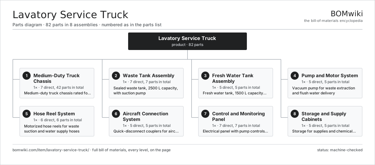
| # | Part | Qty | What it does |
|---|---|---|---|
| 1 | Medium-Duty Truck Chassis 7 parts | 1× | Medium-duty truck chassis rated for 4000 kg payload |
| 2 | Waste Tank Assembly 7 parts | 1× | Sealed waste tank, 2500 L capacity, with suction pump |
| 3 | Fresh Water Tank Assembly 5 parts | 1× | Fresh water tank, 1500 L capacity, pressurized |
| 4 | Pump and Motor System 5 parts | 1× | Vacuum pump for waste extraction and flush water delivery |
| 5 | Hose Reel System 6 parts | 1× | Motorized hose reels for waste suction and water supply hoses |
| 6 | Aircraft Connection System 5 parts | 1× | Quick-disconnect couplers for aircraft lavatory service ports |
| 7 | Control and Monitoring Panel 7 parts | 1× | Electrical panel with pump controls and tank level indicators |
| 8 | Storage and Supply Cabinets 5 parts | 1× | Storage for supplies and chemical additives |
3D model
No 3D model yet. Have a CAD file of this? Add a 3D model — STL renders right on this page; STEP, FreeCAD, and OpenSCAD sources are welcome too (openly licensed, like all 3D models on BOMwiki).
Build & assembly graph
expand / collapse · shared sub-assemblies converge · links to related products · est. labourTap an assembly to expand/collapse · tap a part to open it · use “Open page” for any node · drag to pan, scroll to zoom.
Bill of materials for Lavatory Service Truck
8 top-level lines · 60 rows shown · 82 parts total · indented to 3 levels| # | Item / sub-assembly | Part no. | Qty/assy | Ext. qty | Parts | Type |
|---|---|---|---|---|---|---|
| 1 | Medium-Duty Truck Chassis 7 parts | lavatory-service-truck-chassis | 1× | 1 | 42 | assembly |
| 1.1 | Diesel Engine | lavatory-service-truck-engine | 1× | 1 | · | part |
| 1.2 | Automatic Transmission | lavatory-service-truck-transmission | 1× | 1 | · | part |
| 1.3 | Chassis Frame | lavatory-service-truck-frame | 1× | 1 | · | part |
| 1.4 | Suspension System | lavatory-service-truck-suspension | 1× | 1 | · | part |
| 1.5 | Brake System | lavatory-service-truck-brakes | 1× | 1 | · | part |
| 1.6 | Power Steering | lavatory-service-truck-steering | 1× | 1 | · | part |
| 1.7 | Wheel Assembly 5 parts | wheel-assembly | 4× | 4 | 9 | assembly |
| 1.7.1 | Alloy Wheel | alloy-wheel | 1× | 4 | · | part |
| 1.7.2 | Tire | tire | 1× | 4 | · | part |
| 1.7.3 | TPMS Sensor | tpms-sensor | 1× | 4 | · | part |
| 1.7.4 | Lug Nut | lug-nut | 5× | 20 | · | part |
| 1.7.5 | Valve Stem | valve-stem | 1× | 4 | · | part |
| 2 | Waste Tank Assembly 7 parts | lavatory-service-truck-waste-tank | 1× | 1 | 7 | assembly |
| 2.1 | Waste Tank Container | lavatory-service-truck-waste-shell | 1× | 1 | · | part |
| 2.2 | Baffles | lavatory-service-truck-waste-baffle | 1× | 1 | · | part |
| 2.3 | Waste Inlet | lavatory-service-truck-waste-filler | 1× | 1 | · | part |
| 2.4 | Waste Drain Valve | lavatory-service-truck-waste-drain | 1× | 1 | · | part |
| 2.5 | Level Sensor | lavatory-service-truck-level-sensor | 1× | 1 | · | part |
| 2.6 | Overflow Relief | lavatory-service-truck-overflow-relief | 1× | 1 | · | part |
| 2.7 | Thermal Fuse | thermal-fuse | 1× | 1 | · | part |
| 3 | Fresh Water Tank Assembly 5 parts | lavatory-service-truck-water-tank | 1× | 1 | 5 | assembly |
| 3.1 | Water Tank Container | lavatory-service-truck-water-shell | 1× | 1 | · | part |
| 3.2 | Water Filler | lavatory-service-truck-water-filler | 1× | 1 | · | part |
| 3.3 | Water Drain Valve | lavatory-service-truck-water-drain | 1× | 1 | · | part |
| 3.4 | Pressure Tank | lavatory-service-truck-pressure-tank | 1× | 1 | · | part |
| 3.5 | Pressure Sensor | pressure-sensor | 1× | 1 | · | part |
| 4 | Pump and Motor System 5 parts | lavatory-service-truck-pump | 1× | 1 | 5 | assembly |
| 4.1 | Electric Motor | lavatory-service-truck-motor | 1× | 1 | · | part |
| 4.2 | Vacuum Pump | lavatory-service-truck-vacuum-pump | 1× | 1 | · | part |
| 4.3 | Gear Pump | lavatory-service-truck-displacement-pump | 1× | 1 | · | part |
| 4.4 | Directional Valve | lavatory-service-truck-solenoid-valve | 1× | 1 | · | part |
| 4.5 | Check Valve | lavatory-service-truck-check-valve | 1× | 1 | · | part |
| 5 | Hose Reel System 6 parts | lavatory-service-truck-hose-reels | 1× | 1 | 6 | assembly |
| 5.1 | Waste Hose Reel | lavatory-service-truck-waste-hose-reel | 1× | 1 | · | part |
| 5.2 | Water Hose Reel | lavatory-service-truck-water-hose-reel | 1× | 1 | · | part |
| 5.3 | Reel Motor | lavatory-service-truck-reel-motor | 1× | 1 | · | part |
| 5.4 | Suction Hose | lavatory-service-truck-hose-suction | 1× | 1 | · | part |
| 5.5 | Water Delivery Hose | lavatory-service-truck-hose-water | 1× | 1 | · | part |
| 5.6 | Hose Routing Guides | lavatory-service-truck-hose-guides | 1× | 1 | · | part |
| 6 | Aircraft Connection System 5 parts | lavatory-service-truck-connections | 1× | 1 | 5 | assembly |
| 6.1 | Waste Suction Coupler | lavatory-service-truck-waste-coupler | 1× | 1 | · | part |
| 6.2 | Water Supply Coupler | lavatory-service-truck-water-coupler | 1× | 1 | · | part |
| 6.3 | Ground Cable | lavatory-service-truck-ground-cable | 1× | 1 | · | part |
| 6.4 | Dip Stick | lavatory-service-truck-dip-stick | 1× | 1 | · | part |
| 6.5 | Spill Kit | lavatory-service-truck-spillage-container | 1× | 1 | · | part |
| 7 | Control and Monitoring Panel 7 parts | lavatory-service-truck-control-panel | 1× | 1 | 7 | assembly |
| 7.1 | Pump On/Off Switch | lavatory-service-truck-pump-switch | 1× | 1 | · | part |
| 7.2 | Mode Selector Switch | lavatory-service-truck-solenoid-switch | 1× | 1 | · | part |
| 7.3 | Waste Tank Level Gauge | lavatory-service-truck-level-gauge | 1× | 1 | · | part |
| 7.4 | Water Tank Level Gauge | lavatory-service-truck-water-gauge | 1× | 1 | · | part |
| 7.5 | Water Pressure Gauge | lavatory-service-truck-pressure-gauge | 1× | 1 | · | part |
| 7.6 | Emergency Stop | lavatory-service-truck-emergency-stop | 1× | 1 | · | part |
| 7.7 | Hour Meter | lavatory-service-truck-hour-meter | 1× | 1 | · | part |
| 8 | Storage and Supply Cabinets 5 parts | lavatory-service-truck-cabinets | 1× | 1 | 5 | assembly |
| 8.1 | Supply Cabinet | lavatory-service-truck-supply-cabinet | 1× | 1 | · | part |
| 8.2 | Chemical Storage | lavatory-service-truck-chemical-shelf | 1× | 1 | · | part |
| 8.3 | Tool Rack | lavatory-service-truck-tool-rack | 1× | 1 | · | part |
| 8.4 | Waste Bags | lavatory-service-truck-waste-bags | 1× | 1 | · | part |
| 8.5 | Fastener Set | fastener-set | 1× | 1 | · | part |
Related products
same domain, ranked by shared parts Passenger Boarding Stairs
104 parts · shares 2 with this page
Passenger Boarding Stairs
104 parts · shares 2 with this page
 Airport Pushback Tractor
250 parts · shares 1 with this page
Airport Pushback Tractor
250 parts · shares 1 with this page
 Belt Loader
87 parts · shares 1 with this page
Belt Loader
87 parts · shares 1 with this page
 Aircraft De-Icing Truck
100 parts · shares 1 with this page
Aircraft De-Icing Truck
100 parts · shares 1 with this page
 Airport Catering Truck
115 parts · shares 1 with this page
Airport Catering Truck
115 parts · shares 1 with this page
 Jet Bridge
62 parts · shares 1 with this page
Jet Bridge
62 parts · shares 1 with this page
Sourcing: possible vendors
Prices, MOQ, and lead times are algorithmic estimates, not quotes, and not claims about these companies. Company mappings are curated by keyword; est. price band $30k–$1.5M. How estimates work| Vendor | HQ | Specialty | MOQ | Lead time |
|---|---|---|---|---|
| oshkoshaerotech.com ↗ | Orlando, US | Airport ground support | made to order | 16–30 wks |
| tld-group.com ↗ | Paris, FR | Ground support equipment | made to order | 16–30 wks |
| textrongse.txtsv.com ↗ | Augusta, US | Ground support equipment | made to order | 16–30 wks |
| vestergaardcompany.com ↗ | Skanderborg, DK | De-icers & GSE | made to order | 16–30 wks |
| mallaghangse.com ↗ | Dungannon, GB | Ground support equipment | made to order | 16–30 wks |
1,413-word article