Smart Parcel Locker
ProductOverview
A smart parcel locker replaces the failed-delivery loop with a machine. The courier scans a parcel at the User Terminal, a door pops open, the parcel goes in, and the recipient gets a one-time code; they collect at any hour by scanning the code or typing it on the Metal Keypad. One courier visit serves dozens of households, which is why locker networks such as those in Poland and the Baltics carry a double-digit share of national parcel volume and why a single van round can drop 800 parcels instead of 150.
Physically the product is a bank of steel columns. One column is the terminal; the rest are Locker Module Columns of mixed-size Locker Compartment boxes, from letter slots to 38 cm parcel doors, bolted side by side on a common Plinth Frame. Banks grow by adding columns, and large sites run several hundred compartments off one Main Controller.
How it works
Each compartment is electrically simple: a spring-assisted Compartment Door, a solenoid Electronic Latch, a Door State Switch reporting whether the door is physically shut, and an Occupancy Sensor confirming something is inside. The latch is normally locked and unpowered; opening it costs a 0.5–2 second pulse from the column's Lock Driver Board, which addresses up to 16 latches over an RS-485 Column Bus Cable daisy-chained back to the controller. A Hall Sensor in each latch reports the cam position, so the system distinguishes "unlocked but still shut" from "open" from "shut but never relocked", the difference between a clean transaction and a support ticket.
The deposit flow shows the choreography. The courier authenticates at the terminal, scans the parcel label with the Barcode Scanner Module, and the application picks a free compartment of the right size from its local database. The lock board fires that latch, the spring swings the door open, the courier loads the parcel and shuts the door. Only when the door switch reads closed, the latch reads relocked, and the occupancy sensor reads occupied does the controller commit the transaction and notify the platform, which sends the recipient their QR code. Pickup is the mirror image, ending with occupancy reading empty.
Electronics and resilience
The Main Controller pairs an application processor on a Compute SoC Module with an Microcontroller coprocessor that owns the real-time lock bus. The design assumption is intermittent connectivity: reservations and valid codes are cached locally, every event is appended to the journal on the Storage Module, and the LTE Modem syncs whenever the network allows, failing over between two SIMs in the Dual-SIM Holder. A battery-backed RTC Module keeps code-expiry times honest through outages.
Power architecture follows the same logic. A 24 V Power Supply feeds a fused Power Distribution Board board with separate rails for controller, terminal, locks, and lighting; a Li-ion Cell, 18650 pack under a BMS Board carries the locker through hours of mains failure. Because latches draw power only when pulsed, an idle 100-compartment bank averages well under 100 W, and pickups keep working on battery even when the screen dims to save energy.
Enclosure and security
Street installation drives the mechanical spec. The Cabinet Enclosure is sealed to IP54 with Door Seal Strip gaskets on every opening, the Roof Cap sheds rain and shades the display, and the plinth's Anchor Set bolts the cabinet to its foundation. The display lives behind bonded safety glass in the Terminal Housing, with a Display Heater keeping the touch layer responsive to −30 °C. Security is layered rather than absolute: the Latch Cam resists prying to roughly a kilonewton, Tamper Switch contacts alarm any service-door opening outside a maintenance session, and the Surveillance Camera above the terminal ties video to transaction timestamps. In practice theft from lockers is rare; the parcels worth stealing are anonymous behind identical doors, and every door event is logged.
Operationally the machines are managed remotely: firmware, compartment-fault flagging (a latch that fails to relock is simply removed from the allocation pool), fill-rate telemetry for network planning, and remote release for stuck pickups. Field service is largely swapping latch units and cleaning the Barcode Scanner Module window.
Smart Parcel Locker parts and their functions
8 top-level parts · 278 parts in total · full bill of materials below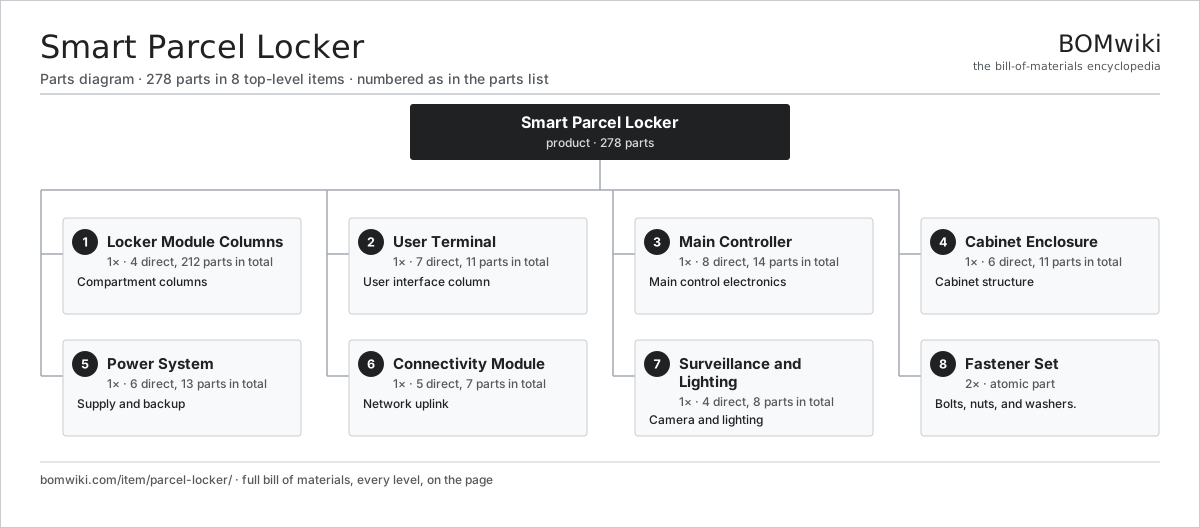
| # | Part | Qty | What it does |
|---|---|---|---|
| 1 | Locker Module Columns 4 parts | 1× | Compartment columns |
| 2 | User Terminal 7 parts | 1× | User interface column |
| 3 | Main Controller 8 parts | 1× | Main control electronics |
| 4 | Cabinet Enclosure 6 parts | 1× | Cabinet structure |
| 5 | Power System 6 parts | 1× | Supply and backup |
| 6 | Connectivity Module 5 parts | 1× | Network uplink |
| 7 | Surveillance and Lighting 4 parts | 1× | Camera and lighting |
| 8 | Fastener Set | 2× | Bolts, nuts, and washers. |
3D model
No 3D model yet. Have a CAD file of this? Add a 3D model. STL renders right on this page; STEP, FreeCAD, and OpenSCAD sources are welcome too (openly licensed, like all 3D models on BOMwiki).
Build & assembly graph
expand / collapse · shared sub-assemblies converge · links to related products · est. labourTap an assembly to expand/collapse · tap a part to open it · use “Open page” for any node · drag to pan, scroll to zoom.
Bill of materials for Smart Parcel Locker
8 top-level lines · 63 rows shown · 278 parts total · indented to 3 levels| # | Item / sub-assembly | Part no. | Qty/assy | Ext. qty | Parts | Type |
|---|---|---|---|---|---|---|
| 1 | Locker Module Columns 4 parts | parcel-locker-modules | 1× | 1 | 212 | assembly |
| 1.1 | Locker Compartment 6 parts | parcel-locker-compartment | 20× | 20 | 10 | assembly |
| 1.1.1 | Compartment Door | parcel-locker-door | 1× | 20 | · | part |
| 1.1.2 | Electronic Latch 5 parts + deeper › | parcel-locker-latch | 1× | 20 | 5 | assembly |
| 1.1.3 | Door State Switch | parcel-locker-door-switch | 1× | 20 | · | part |
| 1.1.4 | Occupancy Sensor | parcel-locker-occupancy-sensor | 1× | 20 | · | part |
| 1.1.5 | Compartment Shelf | parcel-locker-shelf-panel | 1× | 20 | · | part |
| 1.1.6 | Compartment Number Plate | parcel-locker-number-plate | 1× | 20 | · | part |
| 1.2 | Lock Driver Board | parcel-locker-lock-board | 4× | 4 | · | part |
| 1.3 | Column Bus Cable | parcel-locker-bus-cable | 4× | 4 | · | part |
| 1.4 | Column Frame | parcel-locker-column-frame | 4× | 4 | · | part |
| 2 | User Terminal 7 parts | parcel-locker-terminal | 1× | 1 | 11 | assembly |
| 2.1 | LCD Panel | lcd-panel | 1× | 1 | · | part |
| 2.2 | Touch Digitizer | touch-digitizer | 1× | 1 | · | part |
| 2.3 | Barcode Scanner Module 5 parts | parcel-locker-scanner | 1× | 1 | 5 | assembly |
| 2.3.1 | CMOS Image Sensor | image-sensor | 1× | 1 | · | part |
| 2.3.2 | Lens Assembly | camera-lens | 1× | 1 | · | part |
| 2.3.3 | Scanner Illuminator | parcel-locker-scanner-illuminator | 1× | 1 | · | part |
| 2.3.4 | Bare PCB | pcb-bare | 1× | 1 | · | part |
| 2.3.5 | Connector | connector | 1× | 1 | · | part |
| 2.4 | Metal Keypad | parcel-locker-keypad | 1× | 1 | · | part |
| 2.5 | Terminal Housing | parcel-locker-terminal-housing | 1× | 1 | · | part |
| 2.6 | Display Heater | parcel-locker-display-heater | 1× | 1 | · | part |
| 2.7 | Speaker | speaker | 1× | 1 | · | part |
| 3 | Main Controller 8 parts | parcel-locker-controller | 1× | 1 | 14 | assembly |
| 3.1 | Compute SoC Module | soc-module | 1× | 1 | · | part |
| 3.2 | Bare PCB | pcb-bare | 1× | 1 | · | part |
| 3.3 | Microcontroller | mcu | 1× | 1 | · | part |
| 3.4 | Storage Module | parcel-locker-storage-module | 1× | 1 | · | part |
| 3.5 | RTC Module | parcel-locker-rtc-module | 1× | 1 | · | part |
| 3.6 | Tamper Switch | parcel-locker-tamper-switch | 2× | 2 | · | part |
| 3.7 | SMD Passive (R/C/L) | smd-passives | 1× | 1 | · | part |
| 3.8 | Connector | connector | 6× | 6 | · | part |
| 4 | Cabinet Enclosure 6 parts | parcel-locker-enclosure | 1× | 1 | 11 | assembly |
| 4.1 | Sheet Metal Panel | sheet-panel | 6× | 6 | · | part |
| 4.2 | Roof Cap | parcel-locker-roof-cap | 1× | 1 | · | part |
| 4.3 | Plinth Frame | parcel-locker-plinth | 1× | 1 | · | part |
| 4.4 | Service Door | parcel-locker-service-door | 1× | 1 | · | part |
| 4.5 | Anchor Set | parcel-locker-anchor-set | 1× | 1 | · | part |
| 4.6 | Door Seal Strip | parcel-locker-door-seal-strip | 1× | 1 | · | part |
| 5 | Power System 6 parts | parcel-locker-power-system | 1× | 1 | 13 | assembly |
| 5.1 | Power Supply | power-supply | 1× | 1 | · | part |
| 5.2 | Li-ion Cell, 18650 | li-cell-18650 | 8× | 8 | · | part |
| 5.3 | BMS Board | bms-board | 1× | 1 | · | part |
| 5.4 | Power Distribution Board | parcel-locker-power-dist | 1× | 1 | · | part |
| 5.5 | Surge Protector | parcel-locker-surge-protector | 1× | 1 | · | part |
| 5.6 | Wire Bundle | wire-bundle | 1× | 1 | · | part |
| 6 | Connectivity Module 5 parts | parcel-locker-connectivity | 1× | 1 | 7 | assembly |
| 6.1 | LTE Modem | parcel-locker-lte-modem | 1× | 1 | · | part |
| 6.2 | Cellular Antenna | parcel-locker-antenna | 2× | 2 | · | part |
| 6.3 | Dual-SIM Holder | parcel-locker-sim-holder | 1× | 1 | · | part |
| 6.4 | Bare PCB | pcb-bare | 1× | 1 | · | part |
| 6.5 | Connector | connector | 2× | 2 | · | part |
| 7 | Surveillance and Lighting 4 parts | parcel-locker-surveillance | 1× | 1 | 8 | assembly |
| 7.1 | Surveillance Camera 4 parts | parcel-locker-camera | 1× | 1 | 4 | assembly |
| 7.1.1 | CMOS Image Sensor | image-sensor | 1× | 1 | · | part |
| 7.1.2 | Lens Assembly | camera-lens | 1× | 1 | · | part |
| 7.1.3 | Bare PCB | pcb-bare | 1× | 1 | · | part |
| 7.1.4 | Connector | connector | 1× | 1 | · | part |
| 7.2 | LED Light Strip | parcel-locker-led-strip | 2× | 2 | · | part |
| 7.3 | Ambient Light Sensor | parcel-locker-light-sensor | 1× | 1 | · | part |
| 7.4 | Wire Bundle | wire-bundle | 1× | 1 | · | part |
| 8 | Fastener Set | fastener-set | 2× | 2 | · | part |
Something wrong in this list? Report a problem with this BOM.
Related products
same domain, ranked by shared parts Video Intercom System
110 parts · shares 9 with this page
 Video Doorbell
231 parts · shares 7 with this page
 Mantrap Interlock Portal
82 parts · shares 7 with this page
Emergency Call Pillar
43 parts · shares 4 with this page
 Automatic Swing Door Operator
43 parts · shares 6 with this page
 Electronic Key Cabinet
92 parts · shares 6 with this page
Sourcing: possible vendors
Browse the supplier directory → Prices, MOQ, and lead times are algorithmic estimates, not quotes, and not claims about these companies. Company mappings are curated by keyword; est. price band $50–$10k. How estimates work| Vendor | HQ | Specialty | MOQ | Lead time |
|---|---|---|---|---|
| assaabloy.com ↗ | Stockholm, SE | Locks & access | 1,000 units | 8–12 wks |
|
🇺🇸Allegion
allegion.com ↗
|
Dublin, US | Security products (Schlage) | 1,000 units | 8–12 wks |
| dormakaba.com ↗ | Rümlang, CH | Access & door systems | 1,000 units | 8–12 wks |
| honeywell.com ↗ | Charlotte, US | Building & safety tech | 1,000 units | 8–12 wks |
| hikvision.com ↗ | Hangzhou, CN | Surveillance & security | 1,000 units | 8–12 wks |
739-word article