Patch Panel
ProductOverview
A patch panel is the organizing point of a structured cabling system. The permanent cables running through a building's walls and ceilings are stiff, solid-conductor runs that should be terminated once and never disturbed. They all land on the back of a patch panel, and the technician's day-to-day work, connecting a given outlet to a given switch port, happens on the front with short flexible patch cords. This keeps the fragile horizontal wiring untouched while leaving the network endlessly re-arrangeable.
The unit is built around the Mounting Frame, a 1U steel face punched with openings. Each opening holds a Keystone RJ45 Jack whose front is an RJ45 socket and whose rear is a punch-down block; denser panels tie a whole row together on a PCB Termination Strip. Behind the panel a Rear Cable Manager dresses and supports the landed cables, while the Label Strip identifies each port. The Rack Ears fix the panel into the rack and the Grounding Kit bonds it for safety and noise control.
How it works
Termination is mechanical, not soldered. A horizontal cable's four pairs are laid into the insulation-displacement contacts on the jack's rear, and a punch-down tool drives each conductor home; the slotted terminal slices through the insulation and grips the copper in one motion, seating the wire and trimming the excess at the same time. The connection is gas-tight and holds for decades without maintenance.
The harder problem a patch panel solves is keeping a fast signal clean through the break. At Cat 6 and above, the jack carries a small tuned PCB whose trace layout deliberately introduces a small opposing coupling to cancel the crosstalk the connector itself creates, so the link still meets its bandwidth rating. Pair untwisting is kept to the minimum length, shielded variants carry the cable screen through to the bonded panel, and the grounding kit ties everything to the rack's ground bus. The result is a frame full of passive copper that adds almost nothing electrically while making the network trivial to re-wire.
Patch Panel parts and their functions
7 top-level parts · 165 parts in total · full bill of materials below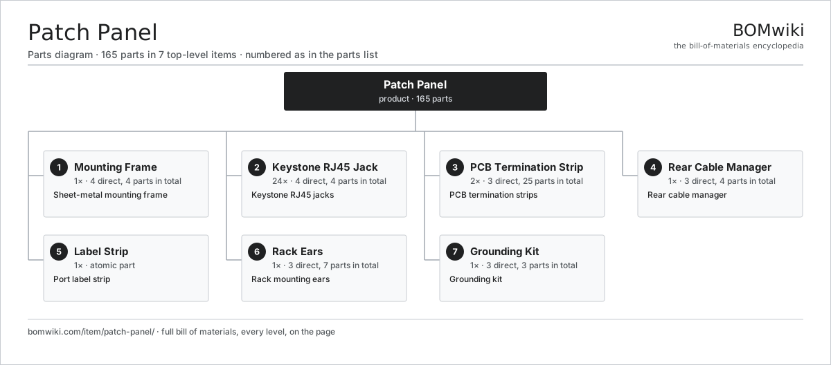
| # | Part | Qty | What it does |
|---|---|---|---|
| 1 | Mounting Frame 4 parts | 1× | Sheet-metal mounting frame |
| 2 | Keystone RJ45 Jack 4 parts | 24× | Keystone RJ45 jacks |
| 3 | PCB Termination Strip 3 parts | 2× | PCB termination strips |
| 4 | Rear Cable Manager 3 parts | 1× | Rear cable manager |
| 5 | Label Strip | 1× | Port label strip |
| 6 | Rack Ears 3 parts | 1× | Rack mounting ears |
| 7 | Grounding Kit 3 parts | 1× | Grounding kit |
3D model
No 3D model yet. Have a CAD file of this? Add a 3D model. STL renders right on this page; STEP, FreeCAD, and OpenSCAD sources are welcome too (openly licensed, like all 3D models on BOMwiki).
Build & assembly graph
expand / collapse · shared sub-assemblies converge · links to related products · est. labourTap an assembly to expand/collapse · tap a part to open it · use “Open page” for any node · drag to pan, scroll to zoom.
Bill of materials for Patch Panel
7 top-level lines · 27 rows shown · 165 parts total · indented to 3 levels| # | Item / sub-assembly | Part no. | Qty/assy | Ext. qty | Parts | Type |
|---|---|---|---|---|---|---|
| 1 | Mounting Frame 4 parts | patch-panel-frame | 1× | 1 | 4 | assembly |
| 1.1 | Sheet Metal Panel | sheet-panel | 1× | 1 | · | part |
| 1.2 | Rear Flange | patch-panel-rear-flange | 1× | 1 | · | part |
| 1.3 | Cable-Tie Bar | patch-panel-tie-bar | 1× | 1 | · | part |
| 1.4 | Fastener Set | fastener-set | 1× | 1 | · | part |
| 2 | Keystone RJ45 Jack 4 parts | patch-panel-jack | 24× | 24 | 4 | assembly |
| 2.1 | RJ45 Contact Set | patch-panel-rj45-contact | 1× | 24 | · | part |
| 2.2 | IDC Block | patch-panel-idc-block | 1× | 24 | · | part |
| 2.3 | Jack PCB | patch-panel-jack-pcb | 1× | 24 | · | part |
| 2.4 | Keystone Shell | patch-panel-jack-shell | 1× | 24 | · | part |
| 3 | PCB Termination Strip 3 parts | patch-panel-term-strip | 2× | 2 | 25 | assembly |
| 3.1 | Bare PCB | pcb-bare | 1× | 2 | · | part |
| 3.2 | IDC Terminal | patch-panel-idc-terminal | 16× | 32 | · | part |
| 3.3 | SMD Passive (R/C/L) | smd-passives | 8× | 16 | · | part |
| 4 | Rear Cable Manager 3 parts | patch-panel-cable-manager | 1× | 1 | 4 | assembly |
| 4.1 | Routing Fingers | patch-panel-mgmt-fingers | 1× | 1 | · | part |
| 4.2 | Bend-Radius Guard | patch-panel-bend-guard | 2× | 2 | · | part |
| 4.3 | Fastener Set | fastener-set | 1× | 1 | · | part |
| 5 | Label Strip | patch-panel-label-strip | 1× | 1 | · | part |
| 6 | Rack Ears 3 parts | patch-panel-rack-ears | 1× | 1 | 7 | assembly |
| 6.1 | Ear Bracket | patch-panel-ear-bracket | 2× | 2 | · | part |
| 6.2 | Cage Nut | patch-panel-cage-nut | 4× | 4 | · | part |
| 6.3 | Fastener Set | fastener-set | 1× | 1 | · | part |
| 7 | Grounding Kit 3 parts | patch-panel-ground-kit | 1× | 1 | 3 | assembly |
| 7.1 | Ground Lug | patch-panel-ground-lug | 1× | 1 | · | part |
| 7.2 | Bonding Strap | patch-panel-ground-strap | 1× | 1 | · | part |
| 7.3 | Fastener Set | fastener-set | 1× | 1 | · | part |
Something wrong in this list? Report a problem with this BOM.
Related products
same domain, ranked by shared parts 5G Base Station
436 parts · shares 1 with this page
Data Center Switch (Spine)
3,264 parts · shares 1 with this page
 DSL Modem Router
56 parts · shares 1 with this page
 Firewall Appliance
82 parts · shares 1 with this page
 Industrial Ethernet Switch
508 parts · shares 1 with this page
 KVM Switch
179 parts · shares 1 with this page
Sourcing: possible vendors
Browse the supplier directory → Prices, MOQ, and lead times are algorithmic estimates, not quotes, and not claims about these companies. Company mappings are curated by keyword; est. price band $30–$50k. How estimates work| Vendor | HQ | Specialty | MOQ | Lead time |
|---|---|---|---|---|
|
🇺🇸Cisco
cisco.com ↗
|
San Jose, US | Networking | 500 units | 8–14 wks |
|
🇺🇸Juniper
juniper.net ↗
|
Sunnyvale, US | Networking | 500 units | 8–14 wks |
| arista.com ↗ | Santa Clara, US | Networking | 500 units | 8–14 wks |
|
🇫🇮Nokia
nokia.com ↗
|
Espoo, FI | Telecom equipment | 500 units | 8–14 wks |
|
🇨🇳Huawei
huawei.com ↗
|
Shenzhen, CN | Networking & telecom | 500 units | 8–14 wks |
361-word article