Satellite Modem
ProductOverview
A satellite modem is the indoor unit of a VSAT terminal: it turns IP packets into a radio carrier the dish can transmit, and turns the faint carrier coming back down from the satellite into packets again. The hard part is that the received signal is weak and Doppler-shifted, and the satellite link is expensive, so the modem leans on heavy forward-error-correction and adaptive coding to wring every usable bit out of the channel. It connects to the outdoor electronics over a single coax cable that carries the L-band signal, a reference tone, and DC power all at once.
How it works
On receive, the L-band carrier comes in on the Port Module coax and enters the L-Band RF Front-End. A Low-Noise Amplifier sets the noise figure, then the Down-Converter mixes the carrier down to an intermediate frequency using a tone from the Frequency Synthesizer, with RF Filter stages rejecting images and out-of-band energy. The conditioned IF reaches the Modem Mainboard, where the IF ADC digitizes it and the Signal-Processing FPGA runs the demodulator: it recovers carrier and symbol timing, demaps the constellation, and decodes the LDPC/BCH code to recover the original bits. The Compute SoC Module reassembles those into IP frames and pushes them onto the LAN.
Transmit runs the chain in reverse: the SoC frames outbound packets, the IF DAC generates the IF waveform, the Up-Converter translates it to L-band, and the Driver Amplifier feeds it out to the dish-mounted up-converter.
Everything hinges on frequency stability, so the Reference Oscillator disciplines the synthesizers and sample clocks. The Front Panel reports carrier lock and signal quality, and the modem runs from its internal Power Supply.
Satellite Modem parts and their functions
7 top-level parts · 807 parts in total · full bill of materials below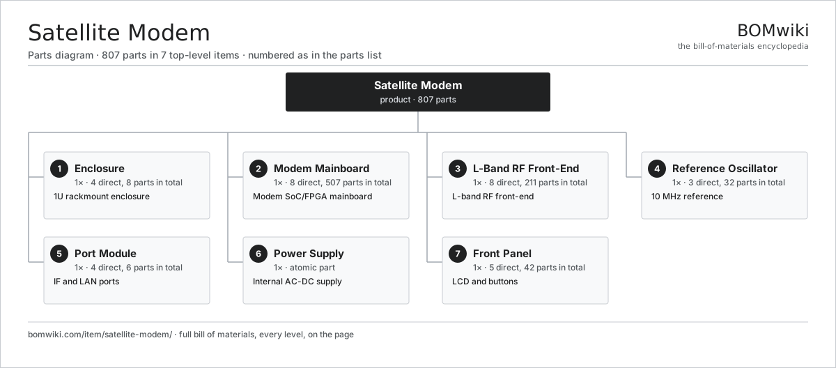
| # | Part | Qty | What it does |
|---|---|---|---|
| 1 | Enclosure 4 parts | 1× | 1U rackmount enclosure |
| 2 | Modem Mainboard 8 parts | 1× | Modem SoC/FPGA mainboard |
| 3 | L-Band RF Front-End 8 parts | 1× | L-band RF front-end |
| 4 | Reference Oscillator 3 parts | 1× | 10 MHz reference |
| 5 | Port Module 4 parts | 1× | IF and LAN ports |
| 6 | Power Supply | 1× | Internal AC-DC supply |
| 7 | Front Panel 5 parts | 1× | LCD and buttons |
Diagrams & photos


3D model
No 3D model yet. Have a CAD file of this? Add a 3D model. STL renders right on this page; STEP, FreeCAD, and OpenSCAD sources are welcome too (openly licensed, like all 3D models on BOMwiki).
Build & assembly graph
expand / collapse · shared sub-assemblies converge · links to related products · est. labourTap an assembly to expand/collapse · tap a part to open it · use “Open page” for any node · drag to pan, scroll to zoom.
Bill of materials for Satellite Modem
7 top-level lines · 39 rows shown · 807 parts total · indented to 3 levels| # | Item / sub-assembly | Part no. | Qty/assy | Ext. qty | Parts | Type |
|---|---|---|---|---|---|---|
| 1 | Enclosure 4 parts | sm-enclosure | 1× | 1 | 8 | assembly |
| 1.1 | Sheet Metal Panel | sheet-panel | 4× | 4 | · | part |
| 1.2 | Rack Mount Ear | sm-rack-ear | 2× | 2 | · | part |
| 1.3 | RF Shield Can | sm-rf-shield | 1× | 1 | · | part |
| 1.4 | Fastener Set | fastener-set | 1× | 1 | · | part |
| 2 | Modem Mainboard 8 parts | sm-mainboard | 1× | 1 | 507 | assembly |
| 2.1 | Bare PCB | pcb-bare | 1× | 1 | · | part |
| 2.2 | Compute SoC Module | soc-module | 1× | 1 | · | part |
| 2.3 | Signal-Processing FPGA | sm-fpga | 1× | 1 | · | part |
| 2.4 | Microcontroller | mcu | 1× | 1 | · | part |
| 2.5 | IF ADC | sm-adc | 1× | 1 | · | part |
| 2.6 | IF DAC | sm-dac | 1× | 1 | · | part |
| 2.7 | Firmware Flash | sm-flash | 1× | 1 | · | part |
| 2.8 | SMD Passive (R/C/L) | smd-passives | 500× | 500 | · | part |
| 3 | L-Band RF Front-End 8 parts | sm-rf-frontend | 1× | 1 | 211 | assembly |
| 3.1 | Bare PCB | pcb-bare | 1× | 1 | · | part |
| 3.2 | Down-Converter | sm-downconverter | 1× | 1 | · | part |
| 3.3 | Up-Converter | sm-upconverter | 1× | 1 | · | part |
| 3.4 | Low-Noise Amplifier | sm-lna | 1× | 1 | · | part |
| 3.5 | Driver Amplifier | sm-pa-driver | 1× | 1 | · | part |
| 3.6 | Frequency Synthesizer | sm-synthesizer | 2× | 2 | · | part |
| 3.7 | RF Filter | sm-rf-filter | 4× | 4 | · | part |
| 3.8 | SMD Passive (R/C/L) | smd-passives | 200× | 200 | · | part |
| 4 | Reference Oscillator 3 parts | sm-reference-oscillator | 1× | 1 | 32 | assembly |
| 4.1 | OCXO | sm-ocxo | 1× | 1 | · | part |
| 4.2 | Bare PCB | pcb-bare | 1× | 1 | · | part |
| 4.3 | SMD Passive (R/C/L) | smd-passives | 30× | 30 | · | part |
| 5 | Port Module 4 parts | sm-port-module | 1× | 1 | 6 | assembly |
| 5.1 | IF Coax Connector | sm-if-connector | 2× | 2 | · | part |
| 5.2 | RJ45 Jack | sm-rj45-jack | 2× | 2 | · | part |
| 5.3 | Ethernet Magnetics | sm-magnetics | 1× | 1 | · | part |
| 5.4 | Connector | connector | 1× | 1 | · | part |
| 6 | Power Supply | power-supply | 1× | 1 | · | part |
| 7 | Front Panel 5 parts | sm-front-panel | 1× | 1 | 42 | assembly |
| 7.1 | Bare PCB | pcb-bare | 1× | 1 | · | part |
| 7.2 | LCD Panel | lcd-panel | 1× | 1 | · | part |
| 7.3 | Push Button | sm-button | 4× | 4 | · | part |
| 7.4 | Status LED | sm-status-led | 6× | 6 | · | part |
| 7.5 | SMD Passive (R/C/L) | smd-passives | 30× | 30 | · | part |
Something wrong in this list? Report a problem with this BOM.
Related products
same domain, ranked by shared parts Firewall Appliance
82 parts · shares 5 with this page
Load Balancer Appliance
911 parts · shares 5 with this page
 Network Switch
1,367 parts · shares 5 with this page
Server Rack
304 parts · shares 4 with this page
5G CPE Router
407 parts · shares 4 with this page
Sourcing: possible vendors
Browse the supplier directory → Prices, MOQ, and lead times are algorithmic estimates, not quotes, and not claims about these companies. Company mappings are curated by keyword; est. price band $30–$50k. How estimates work| Vendor | HQ | Specialty | MOQ | Lead time |
|---|---|---|---|---|
|
🇺🇸Cisco
cisco.com ↗
|
San Jose, US | Networking | 500 units | 8–14 wks |
|
🇺🇸Juniper
juniper.net ↗
|
Sunnyvale, US | Networking | 500 units | 8–14 wks |
| arista.com ↗ | Santa Clara, US | Networking | 500 units | 8–14 wks |
|
🇫🇮Nokia
nokia.com ↗
|
Espoo, FI | Telecom equipment | 500 units | 8–14 wks |
|
🇨🇳Huawei
huawei.com ↗
|
Shenzhen, CN | Networking & telecom | 500 units | 8–14 wks |
294-word article