Power Factor Capacitor Bank
ProductOverview
Inductive loads, motors, transformers, welding sets, draw reactive power that does no useful work but loads the cables and the supply transformer, and that the utility bills for through a poor power factor. A power-factor capacitor bank supplies that reactive power locally, close to the loads, so the upstream network only has to carry the real current. This 250 kVAr bank is automatic and detuned: it switches capacitance in five steps to track the plant's changing reactive demand, and each step is fitted with a series reactor so the bank cannot resonate with harmonics on a modern, electronics-heavy supply.
How it works
The reactive power comes from the Capacitor Power Stage, a set of five Capacitor Step groups, each a three-phase cluster of dry Power Capacitor units forming one 50 kVAr increment. When a step is switched off, its Discharge Resistor bleeds the stored charge down to a safe voltage before anyone could touch the terminals.
Steps are connected and disconnected by the Step Switching stage. Capacitors draw a violent inrush current at the instant of connection, so each step uses a Capacitor-Duty Contactor with pre-charge contacts and an inrush resistor, and is protected against faults by HRC HRC Fuse cartridges. In series with every step sits a Detuning Reactor tuned below the lowest troublesome harmonic, which keeps the capacitors from amplifying harmonic currents.
A Power-Factor Controller is the brain: it measures the line current through its current transformer, computes the running power factor, and switches steps in or out to hold the target. Its display shows the present power factor and which steps are active. Power is distributed across the steps on a Copper Busbar, and the Cooling System fans hold the capacitor compartment within its temperature rating. Everything is built into the vented Enclosure.
Power Factor Capacitor Bank parts and their functions
7 top-level parts · 78 parts in total · full bill of materials below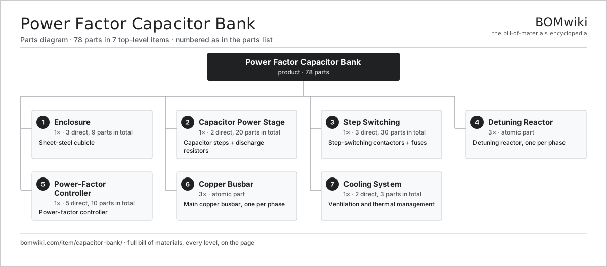
| # | Part | Qty | What it does |
|---|---|---|---|
| 1 | Enclosure 3 parts | 1× | Sheet-steel cubicle |
| 2 | Capacitor Power Stage 2 parts | 1× | Capacitor steps + discharge resistors |
| 3 | Step Switching 3 parts | 1× | Step-switching contactors + fuses |
| 4 | Detuning Reactor | 3× | Detuning reactor, one per phase |
| 5 | Power-Factor Controller 5 parts | 1× | Power-factor controller |
| 6 | Copper Busbar | 3× | Main copper busbar, one per phase |
| 7 | Cooling System 2 parts | 1× | Ventilation and thermal management |
3D model
No 3D model yet. Have a CAD file of this? Add a 3D model. STL renders right on this page; STEP, FreeCAD, and OpenSCAD sources are welcome too (openly licensed, like all 3D models on BOMwiki).
Build & assembly graph
expand / collapse · shared sub-assemblies converge · links to related products · est. labourTap an assembly to expand/collapse · tap a part to open it · use “Open page” for any node · drag to pan, scroll to zoom.
Bill of materials for Power Factor Capacitor Bank
7 top-level lines · 25 rows shown · 78 parts total · indented to 3 levels| # | Item / sub-assembly | Part no. | Qty/assy | Ext. qty | Parts | Type |
|---|---|---|---|---|---|---|
| 1 | Enclosure 3 parts | capbank-enclosure | 1× | 1 | 9 | assembly |
| 1.1 | Sheet Metal Panel | sheet-panel | 6× | 6 | · | part |
| 1.2 | Ventilation Louvre | capbank-louvre | 2× | 2 | · | part |
| 1.3 | Fastener Set | fastener-set | 1× | 1 | · | part |
| 2 | Capacitor Power Stage 2 parts | capbank-power-stage | 1× | 1 | 20 | assembly |
| 2.1 | Capacitor Step 1 parts | capbank-capacitor-step | 5× | 5 | 3 | assembly |
| 2.1.1 | Power Capacitor | capbank-power-capacitor | 3× | 15 | · | part |
| 2.2 | Discharge Resistor | capbank-discharge-resistor | 5× | 5 | · | part |
| 3 | Step Switching 3 parts | capbank-switching | 1× | 1 | 30 | assembly |
| 3.1 | Capacitor-Duty Contactor 2 parts | capbank-contactor | 5× | 5 | 2 | assembly |
| 3.1.1 | Relay | relay | 1× | 5 | · | part |
| 3.1.2 | Power Contact Block | capbank-contact-block | 1× | 5 | · | part |
| 3.2 | HRC Fuse | capbank-fuse | 15× | 15 | · | part |
| 3.3 | Inrush Resistor | capbank-inrush-resistor | 5× | 5 | · | part |
| 4 | Detuning Reactor | capbank-reactor | 3× | 3 | · | part |
| 5 | Power-Factor Controller 5 parts | capbank-controller | 1× | 1 | 10 | assembly |
| 5.1 | Bare PCB | pcb-bare | 1× | 1 | · | part |
| 5.2 | Microcontroller | mcu | 1× | 1 | · | part |
| 5.3 | LCD Panel | lcd-panel | 1× | 1 | · | part |
| 5.4 | Current Transformer | capbank-current-transformer | 1× | 1 | · | part |
| 5.5 | Step Command Relay | capbank-control-relay | 6× | 6 | · | part |
| 6 | Copper Busbar | capbank-busbar | 3× | 3 | · | part |
| 7 | Cooling System 2 parts | capbank-cooling | 1× | 1 | 3 | assembly |
| 7.1 | Ventilation Fan | capbank-fan | 2× | 2 | · | part |
| 7.2 | Thermostat | capbank-thermostat | 1× | 1 | · | part |
Something wrong in this list? Report a problem with this BOM.
Used in 2 assemblies
Related products
same domain, ranked by shared parts Automatic Voltage Regulator
83 parts · shares 2 with this page
Biogas Generator (CHP)
338 parts · shares 2 with this page
Bottom Ash Handling System
1,782 parts · shares 2 with this page
 Combined Heat and Power Unit
522 parts · shares 2 with this page
Sourcing: possible vendors
Browse the supplier directory → Prices, MOQ, and lead times are algorithmic estimates, not quotes, and not claims about these companies. Company mappings are curated by keyword; est. price band $5k–$50M. How estimates work| Vendor | HQ | Specialty | MOQ | Lead time |
|---|---|---|---|---|
| gevernova.com ↗ | Cambridge, US | Power generation | made to order | 20–40 wks |
| siemens-energy.com ↗ | Munich, DE | Power & grid | made to order | 20–40 wks |
| hitachienergy.com ↗ | Zurich, CH | Grid & transformers | made to order | 20–40 wks |
|
🇨🇭ABB
abb.com ↗
|
Zurich, CH | Electrification & automation | made to order | 20–40 wks |
| se.com ↗ | Rueil-Malmaison, FR | Electrical & automation | made to order | 20–40 wks |
306-word article