Cotton Candy Machine
ProductOverview
A cotton candy machine turns ordinary sugar into a cloud of fine threads by melting it and flinging it through tiny holes. At the centre is the Floss Head: sugar poured into its spinner cup is melted by a heated ribbon, then thrown outward by rotation through a perforated band where it cools in mid-air into floss. The Drive Motor spins that head fast, the surrounding Catch Bowl gathers the threads, the Control Board switches motor and heater, and everything sits on a weighted Base that resists the spinning mass.
How it works
Spun sugar exploits the fact that sugar will form glassy strands if it is melted and stretched fast enough to skip recrystallising. Inside the Floss Head, a nichrome Heating Element ribbon wraps the Spinner Cup and brings the sugar to a thin syrup. The head is turning at a few thousand rpm, so centrifugal force drives that syrup outward through the fine holes of the Floss Screen; each hole draws the melt into a thread that solidifies almost instantly in the cooler air and flies outward to the Catch Bowl, where the operator winds it onto a cone or stick.
Because the head spins continuously while carrying a live heater, power cannot reach it through fixed wires. The Slip Ring & Brushes solves this: carbon brushes bear on rotating rings to feed current onto the spinning ribbon. The Drive Motor is a universal motor running on Ball Bearing supports, fed through its own Motor Brushes. The Control Board keeps motor and heat on separate paths through the Brew Buttons, so the head can be brought up to speed before the sugar is heated, which spreads the first melt evenly rather than letting it pool on one side. The weighted Base and its Suction Foot suction cups hold the machine steady against the off-balance forces of the spinning head.
Cotton Candy Machine parts and their functions
5 top-level parts · 127 parts in total · full bill of materials below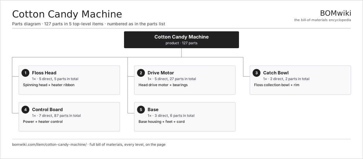
| # | Part | Qty | What it does |
|---|---|---|---|
| 1 | Floss Head 5 parts | 1× | Spinning head + heater ribbon |
| 2 | Drive Motor 5 parts | 1× | Head drive motor + bearings |
| 3 | Catch Bowl 2 parts | 1× | Floss collection bowl + rim |
| 4 | Control Board 7 parts | 1× | Power + heater control |
| 5 | Base 3 parts | 1× | Base housing + feet + cord |
3D model
No 3D model yet. Have a CAD file of this? Add a 3D model. STL renders right on this page; STEP, FreeCAD, and OpenSCAD sources are welcome too (openly licensed, like all 3D models on BOMwiki).
Build & assembly graph
expand / collapse · shared sub-assemblies converge · links to related products · est. labourTap an assembly to expand/collapse · tap a part to open it · use “Open page” for any node · drag to pan, scroll to zoom.
Bill of materials for Cotton Candy Machine
5 top-level lines · 34 rows shown · 127 parts total · indented to 3 levels| # | Item / sub-assembly | Part no. | Qty/assy | Ext. qty | Parts | Type |
|---|---|---|---|---|---|---|
| 1 | Floss Head 5 parts | ccm-floss-head | 1× | 1 | 5 | assembly |
| 1.1 | Spinner Cup | ccm-spinner-cup | 1× | 1 | · | part |
| 1.2 | Heating Element | heating-element | 1× | 1 | · | part |
| 1.3 | Floss Screen | ccm-floss-screen | 1× | 1 | · | part |
| 1.4 | Slip Ring & Brushes | ccm-slip-ring | 1× | 1 | · | part |
| 1.5 | Fastener Set | fastener-set | 1× | 1 | · | part |
| 2 | Drive Motor 5 parts | ccm-drive-motor | 1× | 1 | 27 | assembly |
| 2.1 | Stator Assembly 3 parts | stator-assembly | 1× | 1 | 3 | assembly |
| 2.1.1 | Stator Core (laminations) | stator-core | 1× | 1 | · | part |
| 2.1.2 | Copper Winding | copper-winding | 1× | 1 | · | part |
| 2.1.3 | Slot Insulation | stator-insulation | 1× | 1 | · | part |
| 2.2 | Rotor Assembly 4 parts | rotor-assembly | 1× | 1 | 19 | assembly |
| 2.2.1 | Rotor Shaft | rotor-shaft | 1× | 1 | · | part |
| 2.2.2 | Rotor Core | rotor-core | 1× | 1 | · | part |
| 2.2.3 | Neodymium Magnet | neodymium-magnet | 16× | 16 | · | part |
| 2.2.4 | Ball Bearing | ball-bearing | 1× | 1 | · | part |
| 2.3 | Ball Bearing | ball-bearing | 2× | 2 | · | part |
| 2.4 | Motor Housing | motor-housing | 1× | 1 | · | part |
| 2.5 | Motor Brushes | ccm-motor-brushes | 2× | 2 | · | part |
| 3 | Catch Bowl 2 parts | ccm-catch-bowl | 1× | 1 | 2 | assembly |
| 3.1 | Bowl | ccm-bowl | 1× | 1 | · | part |
| 3.2 | Bowl Rim | ccm-bowl-rim | 1× | 1 | · | part |
| 4 | Control Board 7 parts | ccm-control-board | 1× | 1 | 87 | assembly |
| 4.1 | Bare PCB | pcb-bare | 1× | 1 | · | part |
| 4.2 | Microcontroller | mcu | 1× | 1 | · | part |
| 4.3 | Brew Buttons | ccm-power-switch | 1× | 1 | · | part |
| 4.4 | Relay | relay | 2× | 2 | · | part |
| 4.5 | Triac | triac | 1× | 1 | · | part |
| 4.6 | SMD Passive (R/C/L) | smd-passives | 80× | 80 | · | part |
| 4.7 | Wire Bundle | wire-bundle | 1× | 1 | · | part |
| 5 | Base 3 parts | ccm-base | 1× | 1 | 6 | assembly |
| 5.1 | Base Housing | ccm-base-housing | 1× | 1 | · | part |
| 5.2 | Suction Foot | ccm-foot | 4× | 4 | · | part |
| 5.3 | Mains Cord | ccm-cord | 1× | 1 | · | part |
Something wrong in this list? Report a problem with this BOM.
Related products
same domain, ranked by shared parts Capsule Coffee Machine
123 parts · shares 4 with this page
Super-Automatic Espresso Machine
293 parts · shares 12 with this page
 Espresso Machine
120 parts · shares 11 with this page
 Chocolate Fondue Fountain
110 parts · shares 11 with this page
 Compressor Ice Cream Maker
248 parts · shares 11 with this page
 Electric Milk Frother
125 parts · shares 11 with this page
Sourcing: possible vendors
Browse the supplier directory → Prices, MOQ, and lead times are algorithmic estimates, not quotes, and not claims about these companies. Company mappings are curated by keyword; est. price band $20–$600. How estimates work| Vendor | HQ | Specialty | MOQ | Lead time |
|---|---|---|---|---|
|
🇦🇺Breville
breville.com ↗
|
Sydney, AU | Kitchen appliances | 2,000 units | 6–10 wks |
| groupeseb.com ↗ | Écully, FR | Cookware & small appliances | 2,000 units | 6–10 wks |
| hamiltonbeach.com ↗ | Glen Allen, US | Small appliances | 2,000 units | 6–10 wks |
| panasonic.com ↗ | Osaka, JP | Electronics & appliances | 2,000 units | 6–10 wks |
|
🇨🇳Midea
midea.com ↗
|
Foshan, CN | Home appliances | 2,000 units | 6–10 wks |
327-word article