Electrosurgical Unit
ProductOverview
An electrosurgical unit cuts and coagulates tissue with high-frequency electrical current instead of a blade. When current is concentrated at the fine tip of an active electrode, the tissue right at the tip heats so fast that cells boil and part, a clean cut, while a different waveform heats more gently to seal bleeding vessels. The frequency is kept high, hundreds of kilohertz, so the current passes through the body without stimulating nerves or muscle the way mains-frequency current would. It is one of the most common tools in any operating room.
The core is the RF Generator Board, which produces and controls the waveform. Current leaves through the Output Ports to the surgeon's pencil and returns through the Return Electrode pad. The surgeon selects cut or coag with the Foot Pedal, reads settings on the Display Panel, and the Cooling System system and Power Supply keep the generator running through long cases.
How it works
Power conversion happens on the RF Generator Board. A DC rail from the Power Supply feeds an inverter built from an IGBT Power Module stage, which switches it into a high-frequency square wave. That wave drives the Output Transformer, a ferrite transformer that steps the voltage up to the hundreds, or, for spray coagulation, thousands, of volts needed and isolates the patient from mains. An Microcontroller shapes the waveform: a continuous wave for pure cutting, a bursty low-duty wave for coagulation, and a blend in between.
Holding the effect steady is a closed loop. As tissue dries and chars, its impedance climbs, so the Output Current Sensor feeds the controller, which adjusts drive to keep delivered power on target rather than letting the cut stall or run away. Safety rests on the return path: the Dispersive Pad spreads the returning current over a wide skin area so it does not burn, and the Contact Quality Monitor continuously measures pad impedance, disabling output the moment the pad lifts. The surgeon activates with the Foot Pedal or the handpiece switch read at the Handpiece Jack, adjusts power on the Display Panel, and the Blower Motor in the cooling path carries heat off the power stage during sustained activations.
Electrosurgical Unit parts and their functions
7 top-level parts · 287 parts in total · full bill of materials below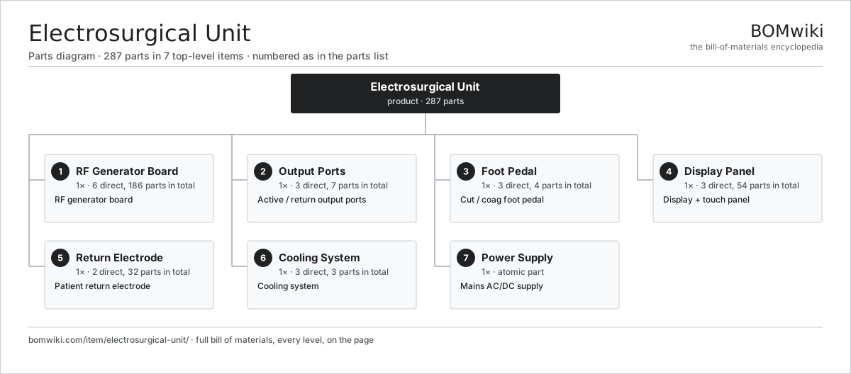
| # | Part | Qty | What it does |
|---|---|---|---|
| 1 | RF Generator Board 6 parts | 1× | RF generator board |
| 2 | Output Ports 3 parts | 1× | Active / return output ports |
| 3 | Foot Pedal 3 parts | 1× | Cut / coag foot pedal |
| 4 | Display Panel 3 parts | 1× | Display + touch panel |
| 5 | Return Electrode 2 parts | 1× | Patient return electrode |
| 6 | Cooling System 3 parts | 1× | Cooling system |
| 7 | Power Supply | 1× | Mains AC/DC supply |
3D model
No 3D model yet. Have a CAD file of this? Add a 3D model. STL renders right on this page; STEP, FreeCAD, and OpenSCAD sources are welcome too (openly licensed, like all 3D models on BOMwiki).
Build & assembly graph
expand / collapse · shared sub-assemblies converge · links to related products · est. labourTap an assembly to expand/collapse · tap a part to open it · use “Open page” for any node · drag to pan, scroll to zoom.
Bill of materials for Electrosurgical Unit
7 top-level lines · 32 rows shown · 287 parts total · indented to 3 levels| # | Item / sub-assembly | Part no. | Qty/assy | Ext. qty | Parts | Type |
|---|---|---|---|---|---|---|
| 1 | RF Generator Board 6 parts | esu-generator-board | 1× | 1 | 186 | assembly |
| 1.1 | Bare PCB | pcb-bare | 1× | 1 | · | part |
| 1.2 | IGBT Power Module | igbt-module | 2× | 2 | · | part |
| 1.3 | Output Transformer | esu-output-transformer | 1× | 1 | · | part |
| 1.4 | Microcontroller | mcu | 1× | 1 | · | part |
| 1.5 | SMD Passive (R/C/L) | smd-passives | 180× | 180 | · | part |
| 1.6 | Output Current Sensor | esu-current-sensor | 1× | 1 | · | part |
| 2 | Output Ports 3 parts | esu-output-ports | 1× | 1 | 7 | assembly |
| 2.1 | Connector | connector | 4× | 4 | · | part |
| 2.2 | Output Relay | esu-port-relay | 2× | 2 | · | part |
| 2.3 | Handpiece Jack | esu-handpiece-jack | 1× | 1 | · | part |
| 3 | Foot Pedal 3 parts | esu-foot-pedal | 1× | 1 | 4 | assembly |
| 3.1 | Pedal Switch | esu-pedal-switch | 2× | 2 | · | part |
| 3.2 | Pedal Housing | esu-pedal-housing | 1× | 1 | · | part |
| 3.3 | Pedal Cable | esu-pedal-cable | 1× | 1 | · | part |
| 4 | Display Panel 3 parts | esu-display | 1× | 1 | 54 | assembly |
| 4.1 | LCD Panel | lcd-panel | 1× | 1 | · | part |
| 4.2 | Touch Digitizer | touch-digitizer | 1× | 1 | · | part |
| 4.3 | Display Board 3 parts | esu-display-board | 1× | 1 | 52 | assembly |
| 4.3.1 | Bare PCB | pcb-bare | 1× | 1 | · | part |
| 4.3.2 | Microcontroller | mcu | 1× | 1 | · | part |
| 4.3.3 | SMD Passive (R/C/L) | smd-passives | 50× | 50 | · | part |
| 5 | Return Electrode 2 parts | esu-return-electrode | 1× | 1 | 32 | assembly |
| 5.1 | Dispersive Pad | esu-return-pad | 1× | 1 | · | part |
| 5.2 | Contact Quality Monitor 2 parts | esu-cqm-board | 1× | 1 | 31 | assembly |
| 5.2.1 | Bare PCB | pcb-bare | 1× | 1 | · | part |
| 5.2.2 | SMD Passive (R/C/L) | smd-passives | 30× | 30 | · | part |
| 6 | Cooling System 3 parts | esu-cooling | 1× | 1 | 3 | assembly |
| 6.1 | Blower Motor | blower-motor | 1× | 1 | · | part |
| 6.2 | Heat Sink | esu-heatsink | 1× | 1 | · | part |
| 6.3 | Air Filter | esu-air-filter | 1× | 1 | · | part |
| 7 | Power Supply | power-supply | 1× | 1 | · | part |
Something wrong in this list? Report a problem with this BOM.
Related products
same domain, ranked by shared parts Neonatal Phototherapy Unit
88 parts · shares 4 with this page
 Bone Densitometer (DXA)
107 parts · shares 4 with this page
 Lithotripter (ESWL)
383 parts · shares 4 with this page
 Mammography System
164 parts · shares 4 with this page
 Mobile C-Arm Fluoroscopy
188 parts · shares 4 with this page
 MRI Scanner
207 parts · shares 3 with this page
Sourcing: possible vendors
Browse the supplier directory → Prices, MOQ, and lead times are algorithmic estimates, not quotes, and not claims about these companies. Company mappings are curated by keyword; est. price band $500–$3M. How estimates work| Vendor | HQ | Specialty | MOQ | Lead time |
|---|---|---|---|---|
| gehealthcare.com ↗ | Chicago, US | Medical imaging & devices | 100 units | 12–20 wks |
| siemens-healthineers.com ↗ | Erlangen, DE | Medical systems | 100 units | 12–20 wks |
|
🇳🇱Philips
philips.com ↗
|
Amsterdam, NL | Health technology | 100 units | 12–20 wks |
| medtronic.com ↗ | Minneapolis, US | Medical devices | 100 units | 12–20 wks |
|
🇨🇳Mindray
mindray.com ↗
|
Shenzhen, CN | Medical devices | 100 units | 12–20 wks |
374-word article