Industrial FDM Printer
ProductOverview
Industrial FDM (Fused Deposition Modeling) printers are large-format thermoplastic extruders designed for production-scale additive manufacturing. Unlike consumer-grade machines, industrial FDM systems prioritize repeatability, material handling, and thermal stability through closed-loop feedback, multi-zone heating, and rigid frame construction. They are commonly used in manufacturing of jigs, functional prototypes, end-use thermoplastic parts, and short-run production batches.
The architecture consists of a sealed heated chamber to prevent draft-induced warping, a precision three-axis Cartesian stage (XY motion via stepper motors, Z via leadscrew), dual independently controlled hotends for color mixing or multi-material work, and a thermostatically regulated build platform. Material is fed from desiccant-controlled bays to prevent moisture ingestion, which degrades part quality.
How it works
Thermoplastic filament is driven through a direct-drive gearbox into the Hotend Assembly, where resistive heating melts the polymer to ~280 °C. A thermocouple in the heating block feeds back to the Control Electronics, maintaining isothermal conditions. Molten filament extrudes through a 0.4 mm nozzle onto the Build Platform, which is preheated to 80–110 °C (depending on material) to promote layer adhesion and reduce thermal shock.
The Motion Gantry lowers the build platform on each completed layer by the target layer height (typically 0.1–0.3 mm) and repositions the nozzle head for the next pass. Stepper motors drive lead screws with sub-micron repeatability. The Thermal Management maintains a 50–80 °C chamber ambient via cartridge heaters and thermocouple feedback, reducing convective cooling and warping stress in tall parts.
After a layer is printed, the Interpass Cooling optionally circulates coolant past the nozzle and extruded bead for interpass thermal control, critical for engineering resins like nylon or carbon-filled compounds. Higher cooling rates reduce layer-bonding time and allow faster overall throughput.
Print files are transferred to the Control Electronics via Ethernet or SD card, and the PLC firmware manages tool path interpolation, heater PID loops, and extrusion multiplier correction. Operator interface is a 7-inch touchscreen showing real-time nozzle temp, bed temp, layer count, and estimated time-to-completion.
Materials & Thermal Requirements
PLA (polylactic acid) requires minimal heated bed (50 °C) and no chamber heating; it is the entry-level material. ABS and engineering-grade nylons (PA6, PA6.6) demand higher bed temps (100–110 °C) and a heated chamber (60–80 °C) to prevent delamination and warping. Carbon-fiber-filled composites exhibit anisotropic shrinkage and benefit from slower cooling rates via the interpass coolant loop.
Dual Extrusion Strategy
Two independent hotends allow simultaneous deposition of different materials (e.g., rigid ABS and soluble support PVA) or color blending via nozzle-height offsets. Each hotend is controlled by the Control Electronics, which selects extrusion rate and temperature per tool. This is more flexible than a single Bowden-tube multi-material selector, but adds complexity and cost.
Desiccant Material Handling
Thermoplastics are hygroscopic: absorbed moisture causes hydrolysis at the melt interface, resulting in brittleness and voids. The Material Bays bays include sealed chambers with replaceable desiccant cartridges (silica-gel or molecular sieve) and low-temperature heater elements to drive off absorbed water. Filament passes through a straightener guide before entering the feeder to eliminate coiling memory.
Closing & Maintenance
The sealed Frame Assembly protects the motion stage and electronics from plastic fumes and dust. Access panels allow removal of the Build Platform for part removal and cleaning. The Thermal Management is protected by Thermal Fuse devices at 95 °C to prevent runaway heating.
Routine maintenance includes nozzle cleaning (cold-pull or acetone soak for ABS), bed leveling verification via inductive probe, and inspection of drive Ball Screw for wear. The cartridge Heating Element units are field-replaceable.
Industrial FDM Printer parts and their functions
8 top-level parts · 98 parts in total · full bill of materials below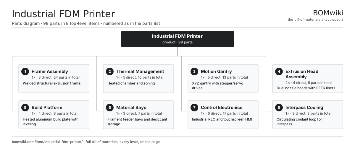
| # | Part | Qty | What it does |
|---|---|---|---|
| 1 | Frame Assembly 3 parts | 1× | Welded structural extrusion frame |
| 2 | Thermal Management 5 parts | 1× | Heated chamber and zoning |
| 3 | Motion Gantry 5 parts | 1× | XYZ gantry with stepper/servo drives |
| 4 | Extrusion Head Assembly 4 parts | 2× | Dual nozzle heads with PEEK liners |
| 5 | Build Platform 4 parts | 1× | Heated aluminum build plate with leveling |
| 6 | Material Bays 3 parts | 1× | Filament feeder bays and desiccant storage |
| 7 | Control Electronics 6 parts | 1× | Industrial PLC and touchscreen HMI |
| 8 | Interpass Cooling 3 parts | 1× | Circulating coolant loop for interpass |
3D model
No 3D model yet. Have a CAD file of this? Add a 3D model. STL renders right on this page; STEP, FreeCAD, and OpenSCAD sources are welcome too (openly licensed, like all 3D models on BOMwiki).
Build & assembly graph
expand / collapse · shared sub-assemblies converge · links to related products · est. labourTap an assembly to expand/collapse · tap a part to open it · use “Open page” for any node · drag to pan, scroll to zoom.
Bill of materials for Industrial FDM Printer
8 top-level lines · 41 rows shown · 98 parts total · indented to 3 levels| # | Item / sub-assembly | Part no. | Qty/assy | Ext. qty | Parts | Type |
|---|---|---|---|---|---|---|
| 1 | Frame Assembly 3 parts | industrial-fdm-printer-frame | 1× | 1 | 24 | assembly |
| 1.1 | Sheet Metal Panel | sheet-panel | 8× | 8 | · | part |
| 1.2 | Fastener Set | fastener-set | 4× | 4 | · | part |
| 1.3 | Ball Bearing | ball-bearing | 12× | 12 | · | part |
| 2 | Thermal Management 5 parts | industrial-fdm-printer-thermal-system | 1× | 1 | 16 | assembly |
| 2.1 | Heating Element | heating-element | 4× | 4 | · | part |
| 2.2 | Pressure Sensor | pressure-sensor | 2× | 2 | · | part |
| 2.3 | Thermal Fuse | thermal-fuse | 2× | 2 | · | part |
| 2.4 | Connector | connector | 6× | 6 | · | part |
| 2.5 | Fastener Set | fastener-set | 2× | 2 | · | part |
| 3 | Motion Gantry 5 parts | industrial-fdm-printer-motion-system | 1× | 1 | 13 | assembly |
| 3.1 | Ball Screw | ball-screw | 3× | 3 | · | part |
| 3.2 | Stepper Motor | stepper-motor | 3× | 3 | · | part |
| 3.3 | Encoder | encoder | 3× | 3 | · | part |
| 3.4 | Hall Sensor | hall-sensor | 2× | 2 | · | part |
| 3.5 | Wire Bundle | wire-bundle | 2× | 2 | · | part |
| 4 | Extrusion Head Assembly 4 parts | industrial-fdm-printer-extrusion-system | 2× | 2 | 5 | assembly |
| 4.1 | Hotend Assembly | industrial-fdm-printer-hotend | 1× | 2 | · | part |
| 4.2 | Blower Motor | blower-motor | 1× | 2 | · | part |
| 4.3 | Motor Housing | motor-housing | 1× | 2 | · | part |
| 4.4 | Fastener Set | fastener-set | 2× | 4 | · | part |
| 5 | Build Platform 4 parts | industrial-fdm-printer-build-platform | 1× | 1 | 8 | assembly |
| 5.1 | Heating Element | heating-element | 2× | 2 | · | part |
| 5.2 | Pressure Sensor | pressure-sensor | 1× | 1 | · | part |
| 5.3 | Connector | connector | 2× | 2 | · | part |
| 5.4 | Fastener Set | fastener-set | 3× | 3 | · | part |
| 6 | Material Bays 3 parts | industrial-fdm-printer-material-handling | 1× | 1 | 7 | assembly |
| 6.1 | Fastener Set | fastener-set | 4× | 4 | · | part |
| 6.2 | Connector | connector | 2× | 2 | · | part |
| 6.3 | Sheet Metal Panel | sheet-panel | 1× | 1 | · | part |
| 7 | Control Electronics 6 parts | industrial-fdm-printer-control-panel | 1× | 1 | 17 | assembly |
| 7.1 | Bare PCB | pcb-bare | 1× | 1 | · | part |
| 7.2 | Microcontroller | mcu | 1× | 1 | · | part |
| 7.3 | Power Supply | power-supply | 2× | 2 | · | part |
| 7.4 | LCD Panel | lcd-panel | 1× | 1 | · | part |
| 7.5 | Relay | relay | 4× | 4 | · | part |
| 7.6 | SMD Passive (R/C/L) | smd-passives | 8× | 8 | · | part |
| 8 | Interpass Cooling 3 parts | industrial-fdm-printer-cooling-system | 1× | 1 | 3 | assembly |
| 8.1 | Coolant Pump | coolant-pump | 1× | 1 | · | part |
| 8.2 | Radiator | radiator | 1× | 1 | · | part |
| 8.3 | Pressure Sensor | pressure-sensor | 1× | 1 | · | part |
Something wrong in this list? Report a problem with this BOM.
Related products
same domain, ranked by shared parts Industrial SLA Printer
94 parts · shares 13 with this page
 Vibratory Bowl Feeder
59 parts · shares 6 with this page
Tire Building Machine
59 parts · shares 6 with this page
WAAM System
83 parts · shares 9 with this page
Binder Jetting Printer
112 parts · shares 14 with this page
Sourcing: possible vendors
Browse the supplier directory → Prices, MOQ, and lead times are algorithmic estimates, not quotes, and not claims about these companies. Company mappings are curated by keyword; est. price band $5k–$2M. How estimates work| Vendor | HQ | Specialty | MOQ | Lead time |
|---|---|---|---|---|
| atlascopco.com ↗ | Stockholm, SE | Compressors & industrial | 10 units | 12–20 wks |
|
🇦🇹Andritz
andritz.com ↗
|
Graz, AT | Process plants & machinery | 10 units | 12–20 wks |
| buhlergroup.com ↗ | Uzwil, CH | Food & materials processing | 10 units | 12–20 wks |
| gea.com ↗ | Düsseldorf, DE | Process technology | 10 units | 12–20 wks |
| mhi.com ↗ | Tokyo, JP | Heavy machinery | 10 units | 12–20 wks |
649-word article