Digital Cinema Camera
ProductOverview
A digital cinema camera is a professional image-capture system designed for high-end film and television production. Unlike consumer cameras, it prioritizes image science, color fidelity, dynamic range, and codec flexibility over size and convenience. This product is a large-format camera: its CMOS Image Sensor measures 36×20 mm (comparable to a 35mm film frame) and captures 6K to 8K resolution with a 12-bit or 14-bit linear color response.
The Optical Bench sits at the heart of the body, holding the CMOS Image Sensor in precise optical alignment. Light enters through an interchangeable Lens Mount Assembly and passes through a ND Filter Wheel containing motorized ND (neutral density) filters that reduce light intensity without altering color, allowing the operator to control exposure without raising ISO and degrading dynamic range. Behind the filters, a Shutter Mechanism spins at a variable angle to control exposure time. Light then falls onto the CMOS Image Sensor, which reads out a high-resolution, high-bit-depth image.
The Image Processing Pipeline processes the raw sensor data in real time: applying color science, gamma correction, and metadata tagging. The Recording System encodes this into a high-quality codec (ProRes 422 HQ or RAW) and writes it to dual SSDs in the Recording Media Bays at bitrates up to 2 Gbps. The operator monitors focus and exposure on the Electronic Viewfinder, an OLED microdisplay with focus-peaking assistance. Timecode and video reference signals are synchronized across the I/O Panel Assembly for integration into multi-camera rigs.
How it works
The CMOS Image Sensor is a rolling-shutter CMOS array with millions of 5–8 micrometer photodiodes. As the mechanical shutter spins, each photodiode accumulates charge from incoming photons. At the end of the shutter window, the charge is quantized to 12 or 14 bits by on-chip analog-to-digital converters and read out line-by-line at high speed (up to 40 gigapixels per second).
The Sensor Readout IC feeds raw Bayer pattern data (alternating red, green, blue pixels) to the Color Matrix FPGA. This FPGA applies demosaicing (inferring RGB at every pixel from the sparse color samples), white balancing (matching the dominant scene illuminant), and a color matrix transform (mapping the sensor's native color gamut to a standard cinema gamut like DCI-P3 or Rec.2020). The output is a linear, high-bit-depth RGB image at full resolution.
The Video Codec Chip ASIC then encodes this image. For ProRes 422 HQ, it applies DCT (discrete cosine transform) compression tuned to visually lossless quality at 500 Mbps; for RAW mode, it writes uncompressed or lightly compressed sensor data directly to disk, preserving maximum flexibility in post-production color grading.
The SSD Controller manages two independent SATA or NVMe interfaces to the Recording Media Bays. A Buffer RAM holds 4–8 GB of video frames in flight, allowing the camera to tolerate brief gaps in SSD write performance without dropping frames. Timecode and metadata are embedded in the bitstream so every frame is tagged with its absolute position on the timeline, synchronizing it with other cameras, audio recorders, and lighting rigs that listen to the I/O Panel Assembly's timecode output.
The Power Distribution converts incoming 12 V from a V-mount battery or external supply to isolated 12 V, 5 V, and 3.3 V rails, powering the sensor, codecs, motors, and fans. Hot-swap capacitor banks provide ride-through during lens or filter changes.
Digital Cinema Camera parts and their functions
12 top-level parts · 305 parts in total · full bill of materials below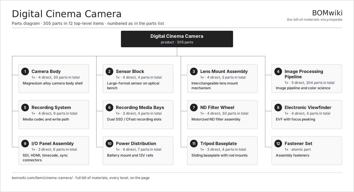
| # | Part | Qty | What it does |
|---|---|---|---|
| 1 | Camera Body 4 parts | 1× | Magnesium alloy camera body shell |
| 2 | Sensor Block 4 parts | 1× | Large-format sensor on optical bench |
| 3 | Lens Mount Assembly 4 parts | 1× | Interchangeable lens mount mechanism |
| 4 | Image Processing Pipeline 5 parts | 1× | Image pipeline and color science |
| 5 | Recording System 4 parts | 1× | Media codec and write path |
| 6 | Recording Media Bays 3 parts | 1× | Dual SSD / CFast recording slots |
| 7 | ND Filter Wheel 4 parts | 1× | Motorized ND filter assembly |
| 8 | Electronic Viewfinder 4 parts | 1× | EVF with focus peaking |
| 9 | I/O Panel Assembly 2 parts | 1× | SDI, HDMI, timecode, sync connectors |
| 10 | Power Distribution 4 parts | 1× | Battery mount and 12V rails |
| 11 | Tripod Baseplate 3 parts | 1× | Sliding baseplate with rod mounts |
| 12 | Fastener Set | 1× | Assembly fasteners |
3D model
No 3D model yet. Have a CAD file of this? Add a 3D model. STL renders right on this page; STEP, FreeCAD, and OpenSCAD sources are welcome too (openly licensed, like all 3D models on BOMwiki).
Build & assembly graph
expand / collapse · shared sub-assemblies converge · links to related products · est. labourTap an assembly to expand/collapse · tap a part to open it · use “Open page” for any node · drag to pan, scroll to zoom.
Bill of materials for Digital Cinema Camera
12 top-level lines · 60 rows shown · 305 parts total · indented to 3 levels| # | Item / sub-assembly | Part no. | Qty/assy | Ext. qty | Parts | Type |
|---|---|---|---|---|---|---|
| 1 | Camera Body 4 parts | cinema-camera-body | 1× | 1 | 30 | assembly |
| 1.1 | Top Cover | cinema-camera-top-cover | 1× | 1 | · | part |
| 1.2 | Side Panel | cinema-camera-side-panels | 2× | 2 | · | part |
| 1.3 | Shutter Mechanism 3 parts | cinema-camera-shutter-assembly | 1× | 1 | 26 | assembly |
| 1.3.1 | Shutter Drum | cinema-camera-shutter-drum | 1× | 1 | · | part |
| 1.3.2 | Servo Motor 4 parts + deeper › | servo-motor | 1× | 1 | 24 | assembly |
| 1.3.3 | Encoder | encoder | 1× | 1 | · | part |
| 1.4 | Fastener Set | fastener-set | 1× | 1 | · | part |
| 2 | Sensor Block 4 parts | cinema-camera-sensor-block | 1× | 1 | 4 | assembly |
| 2.1 | CMOS Image Sensor | image-sensor | 1× | 1 | · | part |
| 2.2 | Sensor Package | cinema-camera-sensor-package | 1× | 1 | · | part |
| 2.3 | Optical Bench | cinema-camera-optical-bench | 1× | 1 | · | part |
| 2.4 | Radiator | radiator | 1× | 1 | · | part |
| 3 | Lens Mount Assembly 4 parts | cinema-camera-lens-mount | 1× | 1 | 5 | assembly |
| 3.1 | Mount Flange | cinema-camera-mount-flange | 1× | 1 | · | part |
| 3.2 | Iris Motor | cinema-camera-iris-motor | 1× | 1 | · | part |
| 3.3 | Focus Motor | cinema-camera-focus-motor | 1× | 1 | · | part |
| 3.4 | Connector | connector | 2× | 2 | · | part |
| 4 | Image Processing Pipeline 5 parts | cinema-camera-imaging-pipeline | 1× | 1 | 204 | assembly |
| 4.1 | Bare PCB | pcb-bare | 1× | 1 | · | part |
| 4.2 | Sensor Readout IC | cinema-camera-sensor-readout-ic | 1× | 1 | · | part |
| 4.3 | Color Matrix FPGA | cinema-camera-color-matrix-fpga | 1× | 1 | · | part |
| 4.4 | SMD Passive (R/C/L) | smd-passives | 200× | 200 | · | part |
| 4.5 | Microcontroller | mcu | 1× | 1 | · | part |
| 5 | Recording System 4 parts | cinema-camera-recording-system | 1× | 1 | 6 | assembly |
| 5.1 | Video Codec Chip | cinema-camera-codec-chip | 1× | 1 | · | part |
| 5.2 | SSD Controller | cinema-camera-ssd-controller | 2× | 2 | · | part |
| 5.3 | Buffer RAM | cinema-camera-ddr-buffer | 1× | 1 | · | part |
| 5.4 | Connector | connector | 2× | 2 | · | part |
| 6 | Recording Media Bays 3 parts | cinema-camera-media-bay | 1× | 1 | 4 | assembly |
| 6.1 | SSD Slot | cinema-camera-ssd-slot | 2× | 2 | · | part |
| 6.2 | Media Bay Door | cinema-camera-media-door | 1× | 1 | · | part |
| 6.3 | Fastener Set | fastener-set | 1× | 1 | · | part |
| 7 | ND Filter Wheel 4 parts | cinema-camera-filter-wheel | 1× | 1 | 30 | assembly |
| 7.1 | Filter Carousel | cinema-camera-filter-carousel | 1× | 1 | · | part |
| 7.2 | Servo Motor 4 parts | servo-motor | 1× | 1 | 24 | assembly |
| 7.2.1 | Stator Assembly 3 parts + deeper › | stator-assembly | 1× | 1 | 3 | assembly |
| 7.2.2 | Rotor Assembly 4 parts + deeper › | rotor-assembly | 1× | 1 | 19 | assembly |
| 7.2.3 | Encoder | encoder | 1× | 1 | · | part |
| 7.2.4 | Motor Housing | motor-housing | 1× | 1 | · | part |
| 7.3 | Encoder | encoder | 1× | 1 | · | part |
| 7.4 | ND Filter | cinema-camera-nd-filter | 4× | 4 | · | part |
| 8 | Electronic Viewfinder 4 parts | cinema-camera-viewfinder | 1× | 1 | 4 | assembly |
| 8.1 | EVF Optics | cinema-camera-evf-panel | 1× | 1 | · | part |
| 8.2 | LCD Panel | lcd-panel | 1× | 1 | · | part |
| 8.3 | Focus Assist IC | cinema-camera-focus-peaking-ic | 1× | 1 | · | part |
| 8.4 | Connector | connector | 1× | 1 | · | part |
| 9 | I/O Panel Assembly 2 parts | cinema-camera-io-panel | 1× | 1 | 6 | assembly |
| 9.1 | Connector | connector | 5× | 5 | · | part |
| 9.2 | Bare PCB | pcb-bare | 1× | 1 | · | part |
| 10 | Power Distribution 4 parts | cinema-camera-power-distribution | 1× | 1 | 7 | assembly |
| 10.1 | Battery Bracket | cinema-camera-battery-bracket | 1× | 1 | · | part |
| 10.2 | Power Supply | power-supply | 1× | 1 | · | part |
| 10.3 | Bulk Capacitor | cinema-camera-bulk-cap | 2× | 2 | · | part |
| 10.4 | Connector | connector | 3× | 3 | · | part |
| 11 | Tripod Baseplate 3 parts | cinema-camera-tripod-plate | 1× | 1 | 4 | assembly |
| 11.1 | Base Plate | cinema-camera-baseplate | 1× | 1 | · | part |
| 11.2 | Rod Bush | cinema-camera-rod-bush | 2× | 2 | · | part |
| 11.3 | Fastener Set | fastener-set | 1× | 1 | · | part |
| 12 | Fastener Set | fastener-set | 1× | 1 | · | part |
Something wrong in this list? Report a problem with this BOM.
Related products
same domain, ranked by shared parts Digital Cinema Projector
383 parts · shares 15 with this page
Terrestrial Laser Scanner
570 parts · shares 15 with this page
 Microfilm Scanner
348 parts · shares 16 with this page
 Industrial 3D Scanner
149 parts · shares 16 with this page
 Camera Motion Control Rig
210 parts · shares 15 with this page
 Laser Tracker
142 parts · shares 15 with this page
Sourcing: possible vendors
Browse the supplier directory → Prices, MOQ, and lead times are algorithmic estimates, not quotes, and not claims about these companies. Company mappings are curated by keyword; est. price band $100–$8k. How estimates work| Vendor | HQ | Specialty | MOQ | Lead time |
|---|---|---|---|---|
|
🇯🇵Canon
canon.com ↗
|
Tokyo, JP | Imaging & optics | 500 units | 10–16 wks |
|
🇯🇵Nikon
nikon.com ↗
|
Tokyo, JP | Imaging & optics | 500 units | 10–16 wks |
|
🇩🇪ZEISS
zeiss.com ↗
|
Oberkochen, DE | Optics & optoelectronics | 500 units | 10–16 wks |
| leica-camera.com ↗ | Wetzlar, DE | Cameras & optics | 500 units | 10–16 wks |
| flir.com ↗ | Wilsonville, US | Thermal imaging | 500 units | 10–16 wks |
597-word article