Fire Hydrant
ProductOverview
A fire hydrant is a fixed connection to a water distribution main that lets firefighters draw large volumes of water for fire suppression. This is a dry-barrel hydrant, the standard type in regions where freezing occurs: the shutoff valve sits buried below the frost line, so the above-ground barrel stays empty between uses and cannot freeze and crack. The operating nut at the top drives a long stem down to a main valve at the base; only when the hydrant is opened does water rise into the barrel and pressurize the nozzles.
The operating mechanism lives in the Upper Barrel & Operating Head, where the bonnet carries the pentagon operating nut, thrust bearing and oil reservoir. The above-ground column is the Barrel Body & Breakaway, split at a traffic flange engineered to shear on vehicle impact. Hose connections are made at the Nozzle Cluster, two 2.5-inch outlets plus a large pumper outlet, each with a chained cap. The Main Valve Assembly is the buried compression valve that actually starts and stops flow, and the Shoe / Base Elbow turns water from the horizontal main up into the barrel. The Drain Valve Assembly automatically empties the barrel when the hydrant is shut.
How it works
To open the hydrant, a firefighter turns the operating nut with a hydrant wrench. The nut rotates the operating stem, which threads the lower plunger downward and lifts the rubber-faced main valve disc off its bronze seat ring. This is a compression valve that opens against system pressure, so water from the main flows up through the shoe and barrel and out the nozzles. As the valve nears full open, the drain ring closes the automatic drain ports so water is not wasted to ground. When the hydrant is shut, the disc reseats on the seat ring, flow stops, and the drain ports reopen to let the column of water in the barrel drain away into the surrounding gravel pocket. The traffic flange and safety stem coupling let the barrel break cleanly away in a collision without rupturing the buried valve or the main.
Fire Hydrant parts and their functions
6 top-level parts · 42 parts in total · full bill of materials below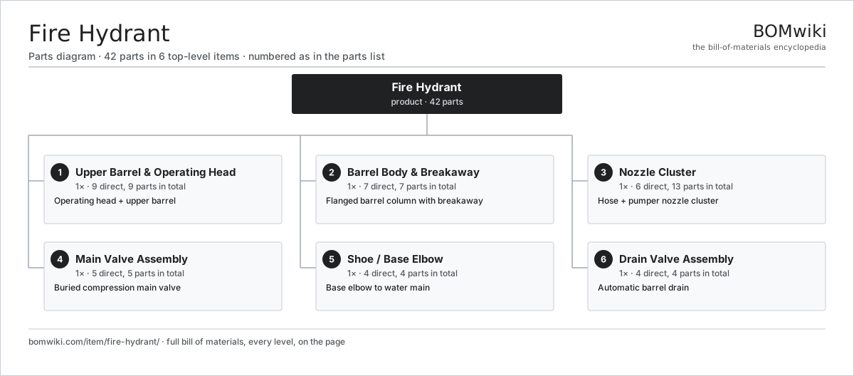
| # | Part | Qty | What it does |
|---|---|---|---|
| 1 | Upper Barrel & Operating Head 9 parts | 1× | Operating head + upper barrel |
| 2 | Barrel Body & Breakaway 7 parts | 1× | Flanged barrel column with breakaway |
| 3 | Nozzle Cluster 6 parts | 1× | Hose + pumper nozzle cluster |
| 4 | Main Valve Assembly 5 parts | 1× | Buried compression main valve |
| 5 | Shoe / Base Elbow 4 parts | 1× | Base elbow to water main |
| 6 | Drain Valve Assembly 4 parts | 1× | Automatic barrel drain |
3D model
No 3D model yet. Have a CAD file of this? Add a 3D model. STL renders right on this page; STEP, FreeCAD, and OpenSCAD sources are welcome too (openly licensed, like all 3D models on BOMwiki).
Build & assembly graph
expand / collapse · shared sub-assemblies converge · links to related products · est. labourTap an assembly to expand/collapse · tap a part to open it · use “Open page” for any node · drag to pan, scroll to zoom.
Bill of materials for Fire Hydrant
6 top-level lines · 41 rows shown · 42 parts total · indented to 3 levels| # | Item / sub-assembly | Part no. | Qty/assy | Ext. qty | Parts | Type |
|---|---|---|---|---|---|---|
| 1 | Upper Barrel & Operating Head 9 parts | fire-hydrant-upper-barrel-assy | 1× | 1 | 9 | assembly |
| 1.1 | Bonnet / Top Cap | fire-hydrant-bonnet | 1× | 1 | · | part |
| 1.2 | Weather Cap | fire-hydrant-weather-cap | 1× | 1 | · | part |
| 1.3 | Operating Nut | fire-hydrant-operating-nut | 1× | 1 | · | part |
| 1.4 | Upper Operating Stem | fire-hydrant-operating-stem-upper | 1× | 1 | · | part |
| 1.5 | Thrust Collar / Bearing | fire-hydrant-thrust-collar | 1× | 1 | · | part |
| 1.6 | Oil Reservoir | fire-hydrant-oil-reservoir | 1× | 1 | · | part |
| 1.7 | Hold-Down Nut | fire-hydrant-hold-down-nut | 1× | 1 | · | part |
| 1.8 | O-Ring Set | oring-set | 1× | 1 | · | part |
| 1.9 | Fastener Set | fastener-set | 1× | 1 | · | part |
| 2 | Barrel Body & Breakaway 7 parts | fire-hydrant-barrel-body-assy | 1× | 1 | 7 | assembly |
| 2.1 | Upper Barrel | fire-hydrant-upper-barrel | 1× | 1 | · | part |
| 2.2 | Lower Barrel | fire-hydrant-lower-barrel | 1× | 1 | · | part |
| 2.3 | Traffic / Breakaway Flange | fire-hydrant-traffic-flange | 1× | 1 | · | part |
| 2.4 | Breakaway Coupling | fire-hydrant-breakaway-coupling | 1× | 1 | · | part |
| 2.5 | Safety Stem Coupling | fire-hydrant-safety-stem-coupling | 1× | 1 | · | part |
| 2.6 | O-Ring Set | oring-set | 1× | 1 | · | part |
| 2.7 | Fastener Set | fastener-set | 1× | 1 | · | part |
| 3 | Nozzle Cluster 6 parts | fire-hydrant-nozzle-assy | 1× | 1 | 13 | assembly |
| 3.1 | Hose Nozzle | fire-hydrant-hose-nozzle | 2× | 2 | · | part |
| 3.2 | Pumper / Steamer Nozzle | fire-hydrant-pumper-nozzle | 1× | 1 | · | part |
| 3.3 | Nozzle Cap | fire-hydrant-nozzle-cap | 3× | 3 | · | part |
| 3.4 | Cap Chain | fire-hydrant-nozzle-chain | 3× | 3 | · | part |
| 3.5 | Nozzle Thread Ring | fire-hydrant-nozzle-thread-ring | 3× | 3 | · | part |
| 3.6 | O-Ring Set | oring-set | 1× | 1 | · | part |
| 4 | Main Valve Assembly 5 parts | fire-hydrant-main-valve-assy | 1× | 1 | 5 | assembly |
| 4.1 | Valve Seat Ring | fire-hydrant-valve-seat-ring | 1× | 1 | · | part |
| 4.2 | Main Valve Disc | fire-hydrant-valve-disc | 1× | 1 | · | part |
| 4.3 | Valve Plunger | fire-hydrant-valve-plunger | 1× | 1 | · | part |
| 4.4 | Drain Ring | fire-hydrant-drain-ring | 1× | 1 | · | part |
| 4.5 | O-Ring Set | oring-set | 1× | 1 | · | part |
| 5 | Shoe / Base Elbow 4 parts | fire-hydrant-shoe-assy | 1× | 1 | 4 | assembly |
| 5.1 | Base Elbow / Shoe | fire-hydrant-base-elbow | 1× | 1 | · | part |
| 5.2 | Inlet Flange | fire-hydrant-inlet-flange | 1× | 1 | · | part |
| 5.3 | O-Ring Set | oring-set | 1× | 1 | · | part |
| 5.4 | Fastener Set | fastener-set | 1× | 1 | · | part |
| 6 | Drain Valve Assembly 4 parts | fire-hydrant-drain-valve-assy | 1× | 1 | 4 | assembly |
| 6.1 | Drain Valve Body | fire-hydrant-drain-valve-body | 1× | 1 | · | part |
| 6.2 | Drain Seat Ring | fire-hydrant-drain-seat | 1× | 1 | · | part |
| 6.3 | Coil Spring | coil-spring | 1× | 1 | · | part |
| 6.4 | O-Ring Set | oring-set | 1× | 1 | · | part |
Something wrong in this list? Report a problem with this BOM.
Related products
same domain, ranked by shared parts Air Ambulance Helicopter
150 parts · shares 1 with this page
 Emergency Escape Breathing Apparatus
23 parts · shares 1 with this page
 Emergency Eyewash Station
89 parts · shares 1 with this page
 Evacuation Chair
87 parts · shares 1 with this page
 Fire Extinguisher
26 parts · shares 1 with this page
 Fire Sprinkler System
554 parts · shares 1 with this page
Sourcing: possible vendors
Browse the supplier directory → Prices, MOQ, and lead times are algorithmic estimates, not quotes, and not claims about these companies. Company mappings are curated by keyword; est. price band $30–$1M. How estimates work| Vendor | HQ | Specialty | MOQ | Lead time |
|---|---|---|---|---|
| rosenbauer.com ↗ | Leonding, AT | Fire apparatus | 200 units | 8–14 wks |
|
🇺🇸Oshkosh
oshkoshcorp.com ↗
|
Oshkosh, US | Specialty trucks (Pierce) | 200 units | 8–14 wks |
| msasafety.com ↗ | Cranberry Township, US | Safety equipment | 200 units | 8–14 wks |
|
🇩🇪Dräger
draeger.com ↗
|
Lübeck, DE | Safety & medical tech | 200 units | 8–14 wks |
| honeywell.com ↗ | Charlotte, US | Building & safety tech | 200 units | 8–14 wks |
362-word article