Aerial Firefighting Tanker
ProductOverview
An aerial firefighting tanker drops water or fire retardant onto wildfires to slow their spread and protect crews on the ground. It flies low and slow over rough terrain, in turbulence and smoke, then releases several tonnes of liquid in a few seconds, so the airframe, the Retardant Tank & Drop System, and the Landing Gear are all built around that punishing duty cycle. This aircraft is a twin Turboprop Engine turboprop with a reinforced Airframe, a belly tank holding about 6,000 litres, and a Water Scoop that can refill the tank by skimming a lake so the crew turns the load around in minutes rather than returning to base each time.
Propulsion and airframe
Turboprops give the tanker the low-speed power and quick throttle response it needs to climb away after a drop and to fly tight patterns in mountainous terrain. Each Turboprop Engine drives a reversible Propeller that helps the aircraft stop short at small remote bases. The Airframe looks like a regional aircraft but the structure is reinforced, because the job is the opposite of airline flying: constant low-level turbulence, repeated hard pull-ups, and the sudden weight change of dropping the entire load at once. The Wing keeps simple high-lift Double-Slotted Flap flaps so the aircraft can fly slowly and precisely over the drop zone.
Retardant tank and drop system
The heart of the aircraft is the Retardant Tank & Drop System. The Retardant Tank sits low in the fuselage and carries internal Anti-Slosh Baffle baffles to stop the liquid sloshing and upsetting the aircraft's balance during maneuvers. The load leaves through several Drop Door doors driven by fast Drop Door Actuator actuators. A Drop Control Computer computer is what makes a drop useful: the pilot selects a coverage level and a volume, and the controller times the doors so the liquid lays down an even line on the ground at the right concentration rather than dumping in one spot. A Tank Vent System lets air into the tank as the liquid leaves so it empties cleanly.
Scooping and refilling
What separates a scooper from a conventional tanker is the Water Scoop. The pilot descends to a lake or wide river, lowers the Scoop Probe probe into the water at speed, and the dynamic pressure forces water up through a Scoop Check Valve into the tank, filling it in roughly twelve seconds without landing. This lets the aircraft cycle between a nearby water source and the fire many times an hour, a far higher drop rate than land-based tankers that must return to an airfield to reload. For longer-lasting effect the Foam Injection Unit unit meters foam concentrate from the Foam Concentrate Tank into the water flow, turning plain water into a clinging fire-suppressing foam.
Cockpit and drop controls
The Flight Deck is a two-pilot flight deck with a dedicated Drop Control Panel beside the standard flight displays. The pilots fly the drop run by eye, lining up on the fire and releasing on a verbal cue or a button, often guided by a lead aircraft or a ground-based air attack supervisor who marks the target. Because drops happen low and in poor visibility from smoke, the workload is high and the margins are small, so the layout keeps the drop controls within easy reach and the Flight Management System flight management system handles navigation between the fire and the water source.
Landing gear, fuel, and systems
The Landing Gear is rugged because tanker bases are often gravel or short rural strips near the fire rather than major airports. Fuel sits in wing Integral Wing Tank tanks kept entirely separate from the retardant, so a leak in one never affects the other. The Aircraft Systems group provides the hydraulics that drive the drop doors and scoop, an electrical system, and an auxiliary power unit for self-sufficient operation at remote bases. The hydraulic system is sized for the drop doors and scoop actuators, which must move fast and reliably on every cycle.
Operations and variants
Aerial tankers do not put fires out by themselves; they buy time and build lines that ground crews then hold. A retardant drop ahead of a fire coats vegetation so the flames slow when they reach it, while a water or foam drop knocks down active flame directly. The fleet ranges from small single-engine air tankers based on agricultural aircraft, through medium twin turboprop scoopers like this one, to very large air tankers converted from airliners that carry tens of thousands of litres in a single load. Scoopers excel where lakes are close and the fire is active, dropping many small loads quickly, while large land-based tankers deliver one enormous load from farther away. Most are seasonal: operators position aircraft and crews near fire-prone regions for the burning season and return them to maintenance and other work afterward, which is why a durable, easily maintained airframe and a simple, reliable Retardant Tank & Drop System matter more than outright performance.
Aerial Firefighting Tanker parts and their functions
8 top-level parts · 1,816 parts in total · full bill of materials below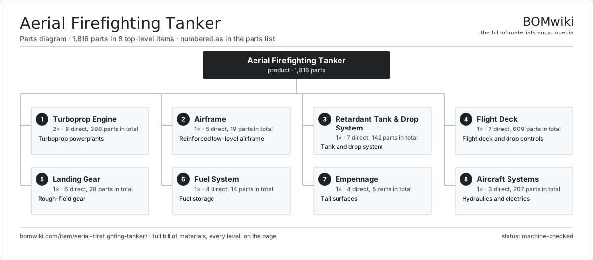
| # | Part | Qty | What it does |
|---|---|---|---|
| 1 | Turboprop Engine 8 parts | 2× | Turboprop powerplants |
| 2 | Airframe 5 parts | 1× | Reinforced low-level airframe |
| 3 | Retardant Tank & Drop System 7 parts | 1× | Tank and drop system |
| 4 | Flight Deck 7 parts | 1× | Flight deck and drop controls |
| 5 | Landing Gear 6 parts | 1× | Rough-field gear |
| 6 | Fuel System 4 parts | 1× | Fuel storage |
| 7 | Empennage 4 parts | 1× | Tail surfaces |
| 8 | Aircraft Systems 3 parts | 1× | Hydraulics and electrics |
3D model
No 3D model yet. Have a CAD file of this? Add a 3D model. STL renders right on this page; STEP, FreeCAD, and OpenSCAD sources are welcome too (openly licensed, like all 3D models on BOMwiki).
Build & assembly graph
expand / collapse · shared sub-assemblies converge · links to related products · est. labourTap an assembly to expand/collapse · tap a part to open it · use “Open page” for any node · drag to pan, scroll to zoom.
Bill of materials for Aerial Firefighting Tanker
8 top-level lines · 118 rows shown · 1,816 parts total · indented to 3 levels| # | Item / sub-assembly | Part no. | Qty/assy | Ext. qty | Parts | Type |
|---|---|---|---|---|---|---|
| 1 | Turboprop Engine 8 parts | aerial-firefighting-tanker-engine | 2× | 2 | 396 | assembly |
| 1.1 | Axial Compressor 3 parts | aerial-firefighting-tanker-compressor | 1× | 2 | 3 | assembly |
| 1.1.1 | Compressor Rotor | military-transport-aircraft-compressor-rotor | 1× | 2 | · | part |
| 1.1.2 | Compressor Stator | military-transport-aircraft-compressor-stator | 1× | 2 | · | part |
| 1.1.3 | Compressor Case | military-transport-aircraft-compressor-case | 1× | 2 | · | part |
| 1.2 | Annular Combustor 3 parts | aerial-firefighting-tanker-combustor | 1× | 2 | 19 | assembly |
| 1.2.1 | Combustor Liner | military-transport-aircraft-combustor-liner | 1× | 2 | · | part |
| 1.2.2 | Fuel Nozzle | heavy-lift-helicopter-fuel-nozzle | 16× | 32 | · | part |
| 1.2.3 | Igniter Plug | heavy-lift-helicopter-igniter | 2× | 4 | · | part |
| 1.3 | Gas Generator Turbine 3 parts | aerial-firefighting-tanker-gas-turbine | 1× | 2 | 121 | assembly |
| 1.3.1 | Turbine Disk | military-transport-aircraft-turbine-disk | 1× | 2 | · | part |
| 1.3.2 | Turbine Blade (cooled) | military-transport-aircraft-turbine-blade | 70× | 140 | · | part |
| 1.3.3 | Nozzle Guide Vane | military-transport-aircraft-nozzle-guide-vane | 50× | 100 | · | part |
| 1.4 | Free Power Turbine | military-transport-aircraft-power-turbine | 1× | 2 | · | part |
| 1.5 | Propeller Reduction Gearbox 6 parts | military-transport-aircraft-prop-gearbox | 1× | 2 | 27 | assembly |
| 1.5.1 | Helical Gear Pair | gear-pair | 3× | 6 | · | part |
| 1.5.2 | Planetary Reduction Stage 5 parts + deeper › | heavy-lift-helicopter-planetary-stage | 1× | 2 | 13 | assembly |
| 1.5.3 | Gearbox Housing | gearbox-housing | 1× | 2 | · | part |
| 1.5.4 | Ball Bearing | ball-bearing | 6× | 12 | · | part |
| 1.5.5 | Oil Seal | oil-seal | 3× | 6 | · | part |
| 1.5.6 | Gear Oil | gear-oil | 1× | 2 | · | part |
| 1.6 | Propeller 4 parts | aerial-firefighting-tanker-propeller | 1× | 2 | 7 | assembly |
| 1.6.1 | Propeller Blade | military-transport-aircraft-prop-blade | 4× | 8 | · | part |
| 1.6.2 | Propeller Hub | military-transport-aircraft-prop-hub | 1× | 2 | · | part |
| 1.6.3 | Pitch Control Unit | military-transport-aircraft-pitch-control | 1× | 2 | · | part |
| 1.6.4 | Spinner | military-transport-aircraft-spinner | 1× | 2 | · | part |
| 1.7 | FADEC Engine Control 4 parts | heavy-lift-helicopter-fadec | 1× | 2 | 210 | assembly |
| 1.7.1 | Bare PCB | pcb-bare | 2× | 4 | · | part |
| 1.7.2 | Microcontroller | mcu | 2× | 4 | · | part |
| 1.7.3 | SMD Passive (R/C/L) | smd-passives | 200× | 400 | · | part |
| 1.7.4 | Connector | connector | 6× | 12 | · | part |
| 1.8 | Ball Bearing | ball-bearing | 8× | 16 | · | part |
| 2 | Airframe 5 parts | aerial-firefighting-tanker-airframe | 1× | 1 | 19 | assembly |
| 2.1 | Fuselage Structure | aerial-firefighting-tanker-fuselage-structure | 1× | 1 | · | part |
| 2.2 | Wing 5 parts | aerial-firefighting-tanker-wing | 2× | 2 | 7 | assembly |
| 2.2.1 | Wing Box | aerial-firefighting-tanker-wing-box | 1× | 2 | · | part |
| 2.2.2 | Wing Skin | aerial-firefighting-tanker-wing-skin | 1× | 2 | · | part |
| 2.2.3 | Double-Slotted Flap | military-transport-aircraft-flap | 2× | 4 | · | part |
| 2.2.4 | Aileron | aerial-firefighting-tanker-aileron | 1× | 2 | · | part |
| 2.2.5 | Spoiler Panel | military-transport-aircraft-spoiler | 2× | 4 | · | part |
| 2.3 | Engine Mount Pylon | military-transport-aircraft-engine-pylon | 2× | 2 | · | part |
| 2.4 | Skin Panel | aerial-firefighting-tanker-skin-panel | 1× | 1 | · | part |
| 2.5 | Fastener Set | fastener-set | 1× | 1 | · | part |
| 3 | Retardant Tank & Drop System 7 parts | aerial-firefighting-tanker-retardant-system | 1× | 1 | 142 | assembly |
| 3.1 | Retardant Tank 4 parts | aerial-firefighting-tanker-tank | 1× | 1 | 10 | assembly |
| 3.1.1 | Tank Shell | aerial-firefighting-tanker-tank-shell | 1× | 1 | · | part |
| 3.1.2 | Anti-Slosh Baffle | aerial-firefighting-tanker-baffle | 6× | 6 | · | part |
| 3.1.3 | Tank Level Sensor | aerial-firefighting-tanker-level-sensor | 2× | 2 | · | part |
| 3.1.4 | O-Ring Set | oring-set | 1× | 1 | · | part |
| 3.2 | Drop Door | aerial-firefighting-tanker-drop-door | 4× | 4 | · | part |
| 3.3 | Drop Door Actuator | aerial-firefighting-tanker-door-actuator | 4× | 4 | · | part |
| 3.4 | Water Scoop 3 parts | aerial-firefighting-tanker-scoop | 2× | 2 | 3 | assembly |
| 3.4.1 | Scoop Probe | aerial-firefighting-tanker-scoop-probe | 1× | 2 | · | part |
| 3.4.2 | Scoop Actuator | aerial-firefighting-tanker-scoop-actuator | 1× | 2 | · | part |
| 3.4.3 | Scoop Check Valve | aerial-firefighting-tanker-check-valve | 1× | 2 | · | part |
| 3.5 | Foam Injection Unit 3 parts | aerial-firefighting-tanker-foam-injection | 1× | 1 | 3 | assembly |
| 3.5.1 | Foam Concentrate Tank | aerial-firefighting-tanker-foam-tank | 1× | 1 | · | part |
| 3.5.2 | Foam Metering Pump | aerial-firefighting-tanker-foam-pump | 1× | 1 | · | part |
| 3.5.3 | Foam Flow Meter | aerial-firefighting-tanker-foam-meter | 1× | 1 | · | part |
| 3.6 | Drop Control Computer 4 parts | aerial-firefighting-tanker-drop-controller | 1× | 1 | 114 | assembly |
| 3.6.1 | Bare PCB | pcb-bare | 1× | 1 | · | part |
| 3.6.2 | Microcontroller | mcu | 1× | 1 | · | part |
| 3.6.3 | SMD Passive (R/C/L) | smd-passives | 100× | 100 | · | part |
| 3.6.4 | Connector | connector | 12× | 12 | · | part |
| 3.7 | Tank Vent System | aerial-firefighting-tanker-vent-system | 1× | 1 | · | part |
| 4 | Flight Deck 7 parts | aerial-firefighting-tanker-cockpit | 1× | 1 | 609 | assembly |
| 4.1 | Multifunction Display 4 parts | military-transport-aircraft-flight-display | 4× | 4 | 83 | assembly |
| 4.1.1 | LCD Panel | lcd-panel | 1× | 4 | · | part |
| 4.1.2 | Bare PCB | pcb-bare | 1× | 4 | · | part |
| 4.1.3 | Microcontroller | mcu | 1× | 4 | · | part |
| 4.1.4 | SMD Passive (R/C/L) | smd-passives | 80× | 320 | · | part |
| 4.2 | Flight Management System 4 parts | military-transport-aircraft-fms | 1× | 1 | 269 | assembly |
| 4.2.1 | Bare PCB | pcb-bare | 2× | 2 | · | part |
| 4.2.2 | Compute SoC Module | soc-module | 1× | 1 | · | part |
| 4.2.3 | SMD Passive (R/C/L) | smd-passives | 250× | 250 | · | part |
| 4.2.4 | Connector | connector | 16× | 16 | · | part |
| 4.3 | Drop Control Panel | aerial-firefighting-tanker-drop-panel | 1× | 1 | · | part |
| 4.4 | Weather Radar | military-transport-aircraft-weather-radar | 1× | 1 | · | part |
| 4.5 | VHF/UHF Radio | heavy-lift-helicopter-radio | 3× | 3 | · | part |
| 4.6 | INS/GPS Navigator | fighter-jet-ins-gps | 1× | 1 | · | part |
| 4.7 | Crew Seat | military-transport-aircraft-crew-seat | 2× | 2 | · | part |
| 5 | Landing Gear 6 parts | aerial-firefighting-tanker-landing-gear | 1× | 1 | 28 | assembly |
| 5.1 | Main Gear Bogie | military-transport-aircraft-main-gear-bogie | 2× | 2 | · | part |
| 5.2 | Nose Gear Leg | fighter-jet-nose-gear | 1× | 1 | · | part |
| 5.3 | Oleo-Pneumatic Strut 4 parts | heavy-lift-helicopter-oleo-strut | 3× | 3 | 4 | assembly |
| 5.3.1 | Strut Cylinder | heavy-lift-helicopter-strut-cylinder | 1× | 3 | · | part |
| 5.3.2 | Strut Piston | heavy-lift-helicopter-strut-piston | 1× | 3 | · | part |
| 5.3.3 | O-Ring Set | oring-set | 1× | 3 | · | part |
| 5.3.4 | Oil Seal | oil-seal | 1× | 3 | · | part |
| 5.4 | Wheel & Tire | military-transport-aircraft-gear-wheel | 6× | 6 | · | part |
| 5.5 | Carbon Wheel Brake | military-transport-aircraft-gear-brake | 4× | 4 | · | part |
| 5.6 | Gear Retract Actuator | military-transport-aircraft-gear-actuator | 3× | 3 | · | part |
| 6 | Fuel System 4 parts | aerial-firefighting-tanker-fuel-system | 1× | 1 | 14 | assembly |
| 6.1 | Integral Wing Tank | military-transport-aircraft-wing-tank | 4× | 4 | · | part |
| 6.2 | Boost Fuel Pump | heavy-lift-helicopter-fuel-pump | 4× | 4 | · | part |
| 6.3 | Fuel Filter | heavy-lift-helicopter-fuel-filter | 2× | 2 | · | part |
| 6.4 | Pressure Sensor | pressure-sensor | 4× | 4 | · | part |
| 7 | Empennage 4 parts | aerial-firefighting-tanker-empennage | 1× | 1 | 5 | assembly |
| 7.1 | Vertical Stabilizer | military-transport-aircraft-vertical-stab | 1× | 1 | · | part |
| 7.2 | Horizontal Stabilizer | military-transport-aircraft-horizontal-stab | 1× | 1 | · | part |
| 7.3 | Rudder | military-transport-aircraft-rudder | 1× | 1 | · | part |
| 7.4 | Elevator | military-transport-aircraft-elevator | 2× | 2 | · | part |
| 8 | Aircraft Systems 3 parts | aerial-firefighting-tanker-systems | 1× | 1 | 207 | assembly |
| 8.1 | Hydraulic System 4 parts | aerial-firefighting-tanker-hydraulics | 1× | 1 | 9 | assembly |
| 8.1.1 | Hydraulic Pump | heavy-lift-helicopter-hydraulic-pump | 2× | 2 | · | part |
| 8.1.2 | Hydraulic Reservoir | heavy-lift-helicopter-hydraulic-reservoir | 2× | 2 | · | part |
| 8.1.3 | Hydraulic Manifold | heavy-lift-helicopter-hydraulic-manifold | 1× | 1 | · | part |
| 8.1.4 | Pressure Sensor | pressure-sensor | 4× | 4 | · | part |
| 8.2 | Electrical System 5 parts | aerial-firefighting-tanker-electrical | 1× | 1 | 195 | assembly |
| 8.2.1 | Integrated Drive Generator | fighter-jet-generator | 2× | 2 | · | part |
| 8.2.2 | Power Distribution Unit 4 parts + deeper › | fighter-jet-power-distribution | 1× | 1 | 141 | assembly |
| 8.2.3 | 12 V Battery | lv-battery | 1× | 1 | · | part |
| 8.2.4 | Wire Bundle | wire-bundle | 1× | 1 | · | part |
| 8.2.5 | Connector | connector | 50× | 50 | · | part |
| 8.3 | Auxiliary Power Unit 3 parts | military-transport-aircraft-apu | 1× | 1 | 3 | assembly |
| 8.3.1 | APU Turbine | military-transport-aircraft-apu-turbine | 1× | 1 | · | part |
| 8.3.2 | Integrated Drive Generator | fighter-jet-generator | 1× | 1 | · | part |
| 8.3.3 | APU Combustor | military-transport-aircraft-apu-combustor | 1× | 1 | · | part |
Related products
same domain, ranked by shared parts Police Cruiser
686 parts · shares 7 with this page
Police Cruiser
686 parts · shares 7 with this page
 Fireboat
236 parts · shares 8 with this page
Fireboat
236 parts · shares 8 with this page
 Fire Engine
547 parts · shares 7 with this page
Fire Engine
547 parts · shares 7 with this page
 Fire Alarm Control Panel
88 parts · shares 5 with this page
Fire Alarm Control Panel
88 parts · shares 5 with this page
 Roadside Assistance Van
463 parts · shares 7 with this page
Roadside Assistance Van
463 parts · shares 7 with this page
 Aerial Ladder Truck
256 parts · shares 6 with this page
Aerial Ladder Truck
256 parts · shares 6 with this page
Sourcing: possible vendors
Browse the supplier directory → Prices, MOQ, and lead times are algorithmic estimates, not quotes, and not claims about these companies. Company mappings are curated by keyword; est. price band $30–$1M. How estimates work| Vendor | HQ | Specialty | MOQ | Lead time |
|---|---|---|---|---|
| rosenbauer.com ↗ | Leonding, AT | Fire apparatus | 200 units | 8–14 wks |
|
🇺🇸Oshkosh
oshkoshcorp.com ↗
|
Oshkosh, US | Specialty trucks (Pierce) | 200 units | 8–14 wks |
| msasafety.com ↗ | Cranberry Township, US | Safety equipment | 200 units | 8–14 wks |
|
🇩🇪Dräger
draeger.com ↗
|
Lübeck, DE | Safety & medical tech | 200 units | 8–14 wks |
| honeywell.com ↗ | Charlotte, US | Building & safety tech | 200 units | 8–14 wks |
902-word article