Fire Sprinkler System
ProductOverview
An automatic fire sprinkler system is a building-wide network of piping and heat-activated sprinklers that detects and controls a fire at its origin, discharging water only over the area that is actually burning. This is a wet-pipe system, meaning the piping is filled with pressurized water at all times so discharge begins the instant a sprinkler opens. Designed to NFPA 13, it combines a supervised water supply, an alarm-sensing riser, a fire pump set and distribution piping feeding sixty pendent heads.
Water enters through the Water Supply Assembly, which carries the backflow preventer and supervised OS&Y isolation valve. It passes the Alarm Check Valve Assembly, a clapper-type alarm check valve whose retard chamber, pressure switch and water motor gong signal flow. Demand flow and pressure are provided by the Fire Pump Set, a centrifugal fire pump with a jockey pump and listed controller. The Piping Network of cross mains and branch lines distributes water to each Sprinkler Head, a frame holding a heat-sensitive glass bulb over a sealed orifice. The Fire Department Connection lets the fire department augment supply, while the Fire Alarm Control Panel supervises the flow and tamper switches.
How it works
Each sprinkler holds a frangible glass bulb filled with a colored liquid that seals a cap against the orifice. Fire heat raises the air temperature at the ceiling; when the bulb reaches its rated temperature, typically 155 °F, the trapped liquid expands and shatters the glass, releasing the cap so water sprays off the deflector in a defined pattern. Only sprinklers over the fire open, limiting water damage. The pressure drop as water flows trips the alarm check valve, which ports water to the pressure switch and the hydraulically driven gong. The fire pump controller starts the main pump on the falling pressure to sustain the rated flow, while the jockey pump handles minor leakage so the main pump is not cycled needlessly. Tamper switches on the control valves report to the panel so a closed valve cannot silently disable the system.
Fire Sprinkler System parts and their functions
12 top-level parts · 554 parts in total · full bill of materials below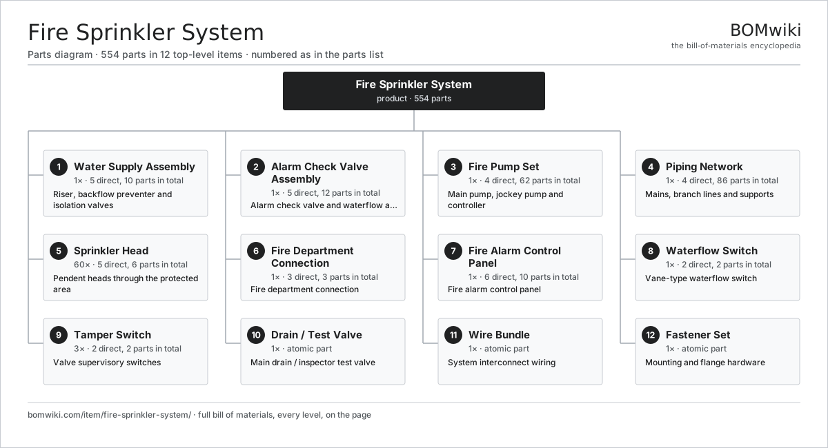
| # | Part | Qty | What it does |
|---|---|---|---|
| 1 | Water Supply Assembly 5 parts | 1× | Riser, backflow preventer and isolation valves |
| 2 | Alarm Check Valve Assembly 5 parts | 1× | Alarm check valve and waterflow alarm |
| 3 | Fire Pump Set 4 parts | 1× | Main pump, jockey pump and controller |
| 4 | Piping Network 4 parts | 1× | Mains, branch lines and supports |
| 5 | Sprinkler Head 5 parts | 60× | Pendent heads through the protected area |
| 6 | Fire Department Connection 3 parts | 1× | Fire department connection |
| 7 | Fire Alarm Control Panel 6 parts | 1× | Fire alarm control panel |
| 8 | Waterflow Switch 2 parts | 1× | Vane-type waterflow switch |
| 9 | Tamper Switch 2 parts | 3× | Valve supervisory switches |
| 10 | Drain / Test Valve | 1× | Main drain / inspector test valve |
| 11 | Wire Bundle | 1× | System interconnect wiring |
| 12 | Fastener Set | 1× | Mounting and flange hardware |
3D model
No 3D model yet. Have a CAD file of this? Add a 3D model. STL renders right on this page; STEP, FreeCAD, and OpenSCAD sources are welcome too (openly licensed, like all 3D models on BOMwiki).
Build & assembly graph
expand / collapse · shared sub-assemblies converge · links to related products · est. labourTap an assembly to expand/collapse · tap a part to open it · use “Open page” for any node · drag to pan, scroll to zoom.
Bill of materials for Fire Sprinkler System
12 top-level lines · 84 rows shown · 554 parts total · indented to 3 levels| # | Item / sub-assembly | Part no. | Qty/assy | Ext. qty | Parts | Type |
|---|---|---|---|---|---|---|
| 1 | Water Supply Assembly 5 parts | fire-sprinkler-system-water-supply | 1× | 1 | 10 | assembly |
| 1.1 | Supply Riser | fire-sprinkler-system-riser | 1× | 1 | · | part |
| 1.2 | Backflow Preventer 3 parts | fire-sprinkler-system-backflow-preventer | 1× | 1 | 4 | assembly |
| 1.2.1 | Backflow Body | fire-sprinkler-system-backflow-body | 1× | 1 | · | part |
| 1.2.2 | Check Valve | fire-sprinkler-system-check-valve | 2× | 2 | · | part |
| 1.2.3 | O-Ring Set | oring-set | 1× | 1 | · | part |
| 1.3 | OS&Y Gate Valve 3 parts | fire-sprinkler-system-osy-gate-valve | 1× | 1 | 3 | assembly |
| 1.3.1 | Gate Valve Body | fire-sprinkler-system-gate-valve-body | 1× | 1 | · | part |
| 1.3.2 | Handwheel | fire-sprinkler-system-handwheel | 1× | 1 | · | part |
| 1.3.3 | O-Ring Set | oring-set | 1× | 1 | · | part |
| 1.4 | Check Valve | fire-sprinkler-system-check-valve | 1× | 1 | · | part |
| 1.5 | Pressure Gauge | fire-sprinkler-system-gauge | 1× | 1 | · | part |
| 2 | Alarm Check Valve Assembly 5 parts | fire-sprinkler-system-alarm-valve-assembly | 1× | 1 | 12 | assembly |
| 2.1 | Alarm Check Valve 5 parts | fire-sprinkler-system-alarm-check-valve | 1× | 1 | 5 | assembly |
| 2.1.1 | Alarm Valve Body | fire-sprinkler-system-alarm-valve-body | 1× | 1 | · | part |
| 2.1.2 | Clapper | fire-sprinkler-system-clapper | 1× | 1 | · | part |
| 2.1.3 | Valve Seat Ring | fire-sprinkler-system-valve-seat | 1× | 1 | · | part |
| 2.1.4 | Coil Spring | coil-spring | 1× | 1 | · | part |
| 2.1.5 | O-Ring Set | oring-set | 1× | 1 | · | part |
| 2.2 | Retard Chamber | fire-sprinkler-system-retard-chamber | 1× | 1 | · | part |
| 2.3 | Water Motor Gong 3 parts | fire-sprinkler-system-water-motor-gong | 1× | 1 | 3 | assembly |
| 2.3.1 | Water Motor | fire-sprinkler-system-water-motor | 1× | 1 | · | part |
| 2.3.2 | Gong Bell | fire-sprinkler-system-gong-bell | 1× | 1 | · | part |
| 2.3.3 | Ball Bearing | ball-bearing | 1× | 1 | · | part |
| 2.4 | Pressure Switch | pressure-switch | 1× | 1 | · | part |
| 2.5 | Pressure Gauge | fire-sprinkler-system-gauge | 2× | 2 | · | part |
| 3 | Fire Pump Set 4 parts | fire-sprinkler-system-fire-pump-set | 1× | 1 | 62 | assembly |
| 3.1 | Centrifugal Fire Pump 3 parts | fire-sprinkler-system-fire-pump | 1× | 1 | 4 | assembly |
| 3.1.1 | Pump Casing & Impeller | fire-sprinkler-system-pump-casing | 1× | 1 | · | part |
| 3.1.2 | Ball Bearing | ball-bearing | 2× | 2 | · | part |
| 3.1.3 | O-Ring Set | oring-set | 1× | 1 | · | part |
| 3.2 | Pump Drive Motor 6 parts | fire-sprinkler-system-pump-motor | 1× | 1 | 27 | assembly |
| 3.2.1 | Stator Assembly 3 parts + deeper › | stator-assembly | 1× | 1 | 3 | assembly |
| 3.2.2 | Rotor Assembly 4 parts + deeper › | rotor-assembly | 1× | 1 | 19 | assembly |
| 3.2.3 | Copper Winding | copper-winding | 1× | 1 | · | part |
| 3.2.4 | Motor Housing | motor-housing | 1× | 1 | · | part |
| 3.2.5 | Ball Bearing | ball-bearing | 2× | 2 | · | part |
| 3.2.6 | O-Ring Set | oring-set | 1× | 1 | · | part |
| 3.3 | Jockey Pump 4 parts | fire-sprinkler-system-jockey-pump | 1× | 1 | 24 | assembly |
| 3.3.1 | Jockey Pump Head | fire-sprinkler-system-jockey-pump-head | 1× | 1 | · | part |
| 3.3.2 | Stator Assembly 3 parts + deeper › | stator-assembly | 1× | 1 | 3 | assembly |
| 3.3.3 | Rotor Assembly 4 parts + deeper › | rotor-assembly | 1× | 1 | 19 | assembly |
| 3.3.4 | Pressure Switch | pressure-switch | 1× | 1 | · | part |
| 3.4 | Fire Pump Controller 5 parts | fire-sprinkler-system-pump-controller | 1× | 1 | 7 | assembly |
| 3.4.1 | Bare PCB | pcb-bare | 1× | 1 | · | part |
| 3.4.2 | Microcontroller | mcu | 1× | 1 | · | part |
| 3.4.3 | Relay | relay | 3× | 3 | · | part |
| 3.4.4 | Pressure Switch | pressure-switch | 1× | 1 | · | part |
| 3.4.5 | Wire Bundle | wire-bundle | 1× | 1 | · | part |
| 4 | Piping Network 4 parts | fire-sprinkler-system-piping-network | 1× | 1 | 86 | assembly |
| 4.1 | Cross Main | fire-sprinkler-system-cross-main | 4× | 4 | · | part |
| 4.2 | Branch Line | fire-sprinkler-system-branch-line | 12× | 12 | · | part |
| 4.3 | Pipe Fitting | fire-sprinkler-system-pipe-fitting | 40× | 40 | · | part |
| 4.4 | Pipe Hanger | fire-sprinkler-system-pipe-hanger | 30× | 30 | · | part |
| 5 | Sprinkler Head 5 parts | fire-sprinkler-system-sprinkler-head | 60× | 60 | 6 | assembly |
| 5.1 | Sprinkler Frame | fire-sprinkler-system-sprinkler-frame | 1× | 60 | · | part |
| 5.2 | Glass Bulb 2 parts | fire-sprinkler-system-glass-bulb | 1× | 60 | 2 | assembly |
| 5.2.1 | Frangible Bulb | fire-sprinkler-system-bulb-glass | 1× | 60 | · | part |
| 5.2.2 | Coil Spring | coil-spring | 1× | 60 | · | part |
| 5.3 | Deflector | fire-sprinkler-system-deflector | 1× | 60 | · | part |
| 5.4 | Seal Cap | fire-sprinkler-system-seal-cap | 1× | 60 | · | part |
| 5.5 | O-Ring Set | oring-set | 1× | 60 | · | part |
| 6 | Fire Department Connection 3 parts | fire-sprinkler-system-fdc | 1× | 1 | 3 | assembly |
| 6.1 | FDC Body | fire-sprinkler-system-fdc-body | 1× | 1 | · | part |
| 6.2 | Check Valve | fire-sprinkler-system-check-valve | 1× | 1 | · | part |
| 6.3 | O-Ring Set | oring-set | 1× | 1 | · | part |
| 7 | Fire Alarm Control Panel 6 parts | fire-sprinkler-system-alarm-panel | 1× | 1 | 10 | assembly |
| 7.1 | Bare PCB | pcb-bare | 1× | 1 | · | part |
| 7.2 | Microcontroller | mcu | 1× | 1 | · | part |
| 7.3 | Relay | relay | 4× | 4 | · | part |
| 7.4 | Standby Battery | fire-sprinkler-system-panel-battery | 1× | 1 | · | part |
| 7.5 | Zone Annunciator 2 parts | fire-sprinkler-system-annunciator | 1× | 1 | 2 | assembly |
| 7.5.1 | Bare PCB | pcb-bare | 1× | 1 | · | part |
| 7.5.2 | Connector | connector | 1× | 1 | · | part |
| 7.6 | Wire Bundle | wire-bundle | 1× | 1 | · | part |
| 8 | Waterflow Switch 2 parts | fire-sprinkler-system-flow-switch | 1× | 1 | 2 | assembly |
| 8.1 | Flow Vane | fire-sprinkler-system-flow-vane | 1× | 1 | · | part |
| 8.2 | Switch Mechanism | fire-sprinkler-system-switch-mechanism | 1× | 1 | · | part |
| 9 | Tamper Switch 2 parts | fire-sprinkler-system-tamper-switch | 3× | 3 | 2 | assembly |
| 9.1 | Tamper Lever | fire-sprinkler-system-tamper-lever | 1× | 3 | · | part |
| 9.2 | Switch Mechanism | fire-sprinkler-system-switch-mechanism | 1× | 3 | · | part |
| 10 | Drain / Test Valve | fire-sprinkler-system-drain-test-valve | 1× | 1 | · | part |
| 11 | Wire Bundle | wire-bundle | 1× | 1 | · | part |
| 12 | Fastener Set | fastener-set | 1× | 1 | · | part |
Something wrong in this list? Report a problem with this BOM.
Related products
same domain, ranked by shared parts Emergency Eyewash Station
89 parts · shares 11 with this page
 Air Ambulance Helicopter
150 parts · shares 10 with this page
 Heavy Recovery Wrecker
308 parts · shares 10 with this page
 Aerial Ladder Truck
256 parts · shares 10 with this page
 Breathing Air Compressor
96 parts · shares 10 with this page
Decontamination Shower System
102 parts · shares 10 with this page
Sourcing: possible vendors
Browse the supplier directory → Prices, MOQ, and lead times are algorithmic estimates, not quotes, and not claims about these companies. Company mappings are curated by keyword; est. price band $30–$1M. How estimates work| Vendor | HQ | Specialty | MOQ | Lead time |
|---|---|---|---|---|
| rosenbauer.com ↗ | Leonding, AT | Fire apparatus | 200 units | 8–14 wks |
|
🇺🇸Oshkosh
oshkoshcorp.com ↗
|
Oshkosh, US | Specialty trucks (Pierce) | 200 units | 8–14 wks |
| msasafety.com ↗ | Cranberry Township, US | Safety equipment | 200 units | 8–14 wks |
|
🇩🇪Dräger
draeger.com ↗
|
Lübeck, DE | Safety & medical tech | 200 units | 8–14 wks |
| honeywell.com ↗ | Charlotte, US | Building & safety tech | 200 units | 8–14 wks |
359-word article