Frost-Free Yard Hydrant
ProductOverview
A frost-free yard hydrant delivers outdoor water through freezing winters by putting its shutoff valve underground, below the frost line, instead of at the spout. The user operates it from the surface, but the actual sealing happens at the bottom of a buried standpipe, and after each use the riser drains itself so there is no water left above the frost line to freeze and split the hydrant.
At grade, the frost-free-hydrant-head carries the spout, the lift handle and the lever linkage. Raising the handle pulls the frost-free-hydrant-operating-rod the full depth of the frost-free-hydrant-standpipe to open the buried frost-free-hydrant-valve. The frost-free-hydrant-weep-hole at the valve body lets the standpipe empty after shutoff, and the frost-free-hydrant-inlet joins the valve to the supply line.
How it works
When the user lifts the handle, the lever linkage draws the operating rod upward. The rod is coupled to the frost-free-hydrant-plunger, which lifts off the brass frost-free-hydrant-valve-seat and lets supply water rise up the standpipe and out the spout. Because the valve sits below the frost line, the seal and the standing supply water are always in unfrozen ground.
Lowering the handle pushes the plunger back down onto the seat and shuts off flow. At that moment the small frost-free-hydrant-weep-hole in the valve body is uncovered, and the water remaining in the standpipe drains out through it into the surrounding gravel bed. Within moments the riser is empty, so even in deep cold there is no trapped water above grade to freeze. An O-ring seals the plunger as it strokes, and adjustable stem packing seals the operating rod where it leaves the head.
This self-draining behavior is the whole point of the design, and it is why a frost-free hydrant must be installed with a gravel drainage pocket and must never have a hose left pressurized on the spout over a freeze, which would block the weep hole and let the standpipe fill and freeze.
Frost-Free Yard Hydrant parts and their functions
7 top-level parts · 16 parts in total · full bill of materials below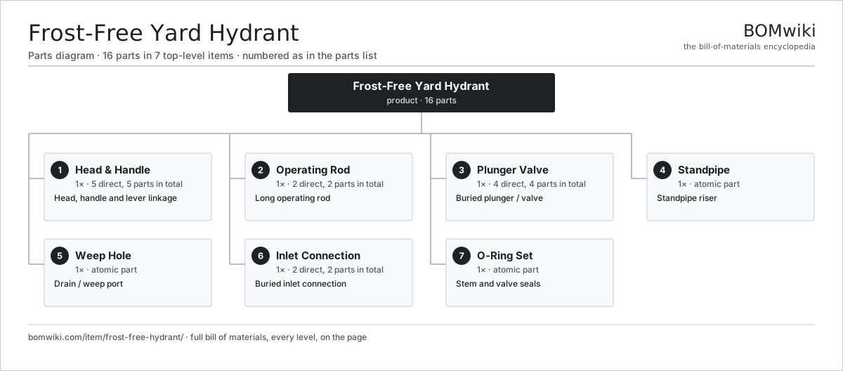
| # | Part | Qty | What it does |
|---|---|---|---|
| 1 | Head & Handle 5 parts | 1× | Head, handle and lever linkage |
| 2 | Operating Rod 2 parts | 1× | Long operating rod |
| 3 | Plunger Valve 4 parts | 1× | Buried plunger / valve |
| 4 | Standpipe | 1× | Standpipe riser |
| 5 | Weep Hole | 1× | Drain / weep port |
| 6 | Inlet Connection 2 parts | 1× | Buried inlet connection |
| 7 | O-Ring Set | 1× | Stem and valve seals |
3D model
No 3D model yet. Have a CAD file of this? Add a 3D model. STL renders right on this page; STEP, FreeCAD, and OpenSCAD sources are welcome too (openly licensed, like all 3D models on BOMwiki).
Build & assembly graph
expand / collapse · shared sub-assemblies converge · links to related products · est. labourTap an assembly to expand/collapse · tap a part to open it · use “Open page” for any node · drag to pan, scroll to zoom.
Bill of materials for Frost-Free Yard Hydrant
7 top-level lines · 20 rows shown · 16 parts total · indented to 3 levels| # | Item / sub-assembly | Part no. | Qty/assy | Ext. qty | Parts | Type |
|---|---|---|---|---|---|---|
| 1 | Head & Handle 5 parts | hydrant-head | 1× | 1 | 5 | assembly |
| 1.1 | Head Casting | hydrant-head-casting | 1× | 1 | · | part |
| 1.2 | Handle | hydrant-handle | 1× | 1 | · | part |
| 1.3 | Lever Linkage | hydrant-lever-linkage | 1× | 1 | · | part |
| 1.4 | Spout | hydrant-spout | 1× | 1 | · | part |
| 1.5 | Stem Packing | hydrant-packing | 1× | 1 | · | part |
| 2 | Operating Rod 2 parts | hydrant-operating-rod | 1× | 1 | 2 | assembly |
| 2.1 | Operating Rod Shaft | hydrant-rod | 1× | 1 | · | part |
| 2.2 | Rod Coupling | hydrant-rod-coupling | 1× | 1 | · | part |
| 3 | Plunger Valve 4 parts | hydrant-valve | 1× | 1 | 4 | assembly |
| 3.1 | Plunger | hydrant-plunger | 1× | 1 | · | part |
| 3.2 | Valve Seat | hydrant-valve-seat | 1× | 1 | · | part |
| 3.3 | Valve Body | hydrant-valve-body | 1× | 1 | · | part |
| 3.4 | O-Ring Set | oring-set | 1× | 1 | · | part |
| 4 | Standpipe | hydrant-standpipe | 1× | 1 | · | part |
| 5 | Weep Hole | hydrant-weep-hole | 1× | 1 | · | part |
| 6 | Inlet Connection 2 parts | hydrant-inlet | 1× | 1 | 2 | assembly |
| 6.1 | Inlet Fitting | hydrant-inlet-fitting | 1× | 1 | · | part |
| 6.2 | O-Ring Set | oring-set | 1× | 1 | · | part |
| 7 | O-Ring Set | oring-set | 1× | 1 | · | part |
Something wrong in this list? Report a problem with this BOM.
Related products
same domain, ranked by shared parts Electric Shower
33 parts · shares 1 with this page
 Electronic Bidet Seat
197 parts · shares 1 with this page
 Grease Interceptor
45 parts · shares 1 with this page
 Greywater Recycling Unit
77 parts · shares 1 with this page
 Heat-Pump Water Heater
152 parts · shares 1 with this page
Sourcing: possible vendors
Browse the supplier directory → Prices, MOQ, and lead times are algorithmic estimates, not quotes, and not claims about these companies. Company mappings are curated by keyword; est. price band $20–$3k. How estimates work| Vendor | HQ | Specialty | MOQ | Lead time |
|---|---|---|---|---|
|
🇺🇸Kohler
kohler.com ↗
|
Kohler, US | Plumbing fixtures | 1,000 units | 6–12 wks |
|
🇯🇵TOTO
toto.com ↗
|
Kitakyushu, JP | Sanitaryware | 1,000 units | 6–12 wks |
|
🇯🇵LIXIL
lixil.com ↗
|
Tokyo, JP | Plumbing (Grohe, American Std) | 1,000 units | 6–12 wks |
|
🇺🇸Moen
moen.com ↗
|
North Olmsted, US | Faucets & fixtures | 1,000 units | 6–12 wks |
|
🇨🇭Geberit
geberit.com ↗
|
Rapperswil, CH | Sanitary systems | 1,000 units | 6–12 wks |
355-word article