Bush Plane
ProductOverview
The Bush Plane is a single-engine utility aircraft built to operate from short, rough, unprepared strips that no other aircraft can use. It carries two people and a useful load of around 550 kg into gravel bars, mountain benches, sandbars, and snow fields, then takes off again in a ground roll that can be under 60 m when lightly loaded. The design is shaped almost entirely by that mission: it needs a very low stall speed so the touchdown and liftoff happen slowly, it needs soft forgiving landing gear that survives rocks and ruts, and it needs to be simple enough to fix in the field with hand tools. Speed and range matter far less, so the airframe trades cruise efficiency for short-field performance and robustness.
The aircraft is built around a welded steel-tube Fuselage, a strut-braced high Wing fitted with high-lift devices, a conventional fabric-covered Empennage, and a piston Piston Engine turning a constant-speed Propeller. It sits on fixed taildragger Landing Gear with oversized soft tires, and the same airframe accepts floats or skis for water and snow work.
Fuselage and Structure
The Fuselage is a TIG-welded Tube Truss of 4130 chromoly steel tube. A welded truss is heavier than a modern aluminium monocoque of the same strength, but it is the right choice here for two reasons: it absorbs crash energy by bending rather than shattering, which protects the occupants in an off-airport accident, and a bent or cracked tube can be cut out and a new one welded in by any competent field shop. The truss is wrapped in a Fabric Covering of polyester that is shrunk tight with heat and sealed with dope, while a removable aluminium Belly Skin shields the underside from stones thrown up on rough ground.
Two wide Cabin Door panels and a large aft Cargo Door make loading easy, including long awkward freight like building materials or a folded canoe. A welded Engine Mount carries the engine forward of a stainless Firewall, and Mount Isolator rubber mounts keep engine vibration out of the airframe. The curved acrylic Windshield and four Side Window panels give the wide downward view a pilot needs to judge an unmarked landing site.
Wing and High Lift
The Wing is the heart of the short-field capability. It is a two-spar aluminium structure: the Wing Spar members carry the bending load, Wing Rib stampings hold the aerofoil shape, and a metal Wing Skin covers the leading edge while Wing Fabric covers the lighter aft section. A streamlined Lift Strut braces the wing to the lower fuselage, which lets the spar be lighter than a cantilever spar carrying the same load.
The wing is loaded with devices that lower the stall speed. A fixed Leading-Edge Slat keeps the airflow attached at the high angles of attack reached on a slow approach, so the wing keeps flying when an ordinary wing would have stalled. A large slotted Flap adds camber and area for the landing, set manually through the cockpit Flap Lever. Rows of small Vortex Generator vanes, part of the STOL kit, stir the boundary layer so it stays attached a few degrees further still. The combined effect drops the full-flap stall to around 53 km/h, which is what makes a 60 m landing possible.
Powerplant and Propeller
The Piston Engine is an air-cooled horizontally-opposed six-cylinder piston engine making about 300 hp. Each Cylinder has a nitrided steel Cylinder Barrel screwed into a cast aluminium Cylinder Head, with two Spark Plug units fired by two independent Magneto units so that the loss of one ignition system does not stop the engine. Fuel and air are mixed by a float Carburetor, and a wet-sump Oil System with an Oil Cooler keeps the bearings fed and the temperature in range. Cabin warmth comes from a Heat Shroud over the Exhaust System, a simple arrangement that costs no weight.
The engine turns a constant-speed Propeller. A Propeller Governor senses propeller speed through a Governor Flyweight pair and drives the Pitch-Change Actuator to change blade angle, holding the speed the pilot set so the propeller absorbs full power on takeoff and runs efficiently in cruise. A coarse blade angle and reverse-capable pitch help slow the aircraft on the ground after a short landing.
Landing Gear and Field Options
The Landing Gear is a fixed taildragger arrangement. The taildragger layout sits the propeller high and nose-up on the ground, which keeps the blades clear of rocks and lets the aircraft be dragged tail-first into a tight parking spot. Each Main Gear Leg uses a flexing spring Gear Leg and a Shock Absorber to soak up a hard arrival, and rolls on an oversized low-pressure Tundra Tire that floats over loose gravel and soft mud that would bog down a normal tire. A steerable Tailwheel linked to the rudder gives ground steering, and a hydraulic Brake Assembly on each main wheel handles the stop.
The wheels are not the only option. A Float Kit with two aluminium Float Hull units and retractable Water Rudder surfaces turns the aircraft into a seaplane for lake and river work, and a Ski Kit fits each Ski over the wheel for landings on snow. Changing between configurations is a planned maintenance task, not a quick swap, but it lets one airframe work year-round across terrain that would otherwise need three different aircraft.
Cockpit and Cabin
The controls are deliberately simple. The Flight Controls use a floor Control Stick, a Rudder Pedal Set set, and direct Push-Rod and Control Cable Run links to the surfaces, with no hydraulics or powered actuation to fail far from help. The panel is just as lean: the Avionics carry a single EFIS Display, a VHF Radio, a GPS Navigator for navigating to unnamed sites, and a Emergency Locator Transmitter beacon that broadcasts position after a crash. A wet Magnetic Compass backs up the electronics. Behind the two crew Seat units the Cabin opens into a reinforced Cargo Floor with Cargo Tie-Down rings, ready to haul supplies into a camp and bring game or freight back out.
Bush Plane parts and their functions
10 top-level parts · 415 parts in total · full bill of materials below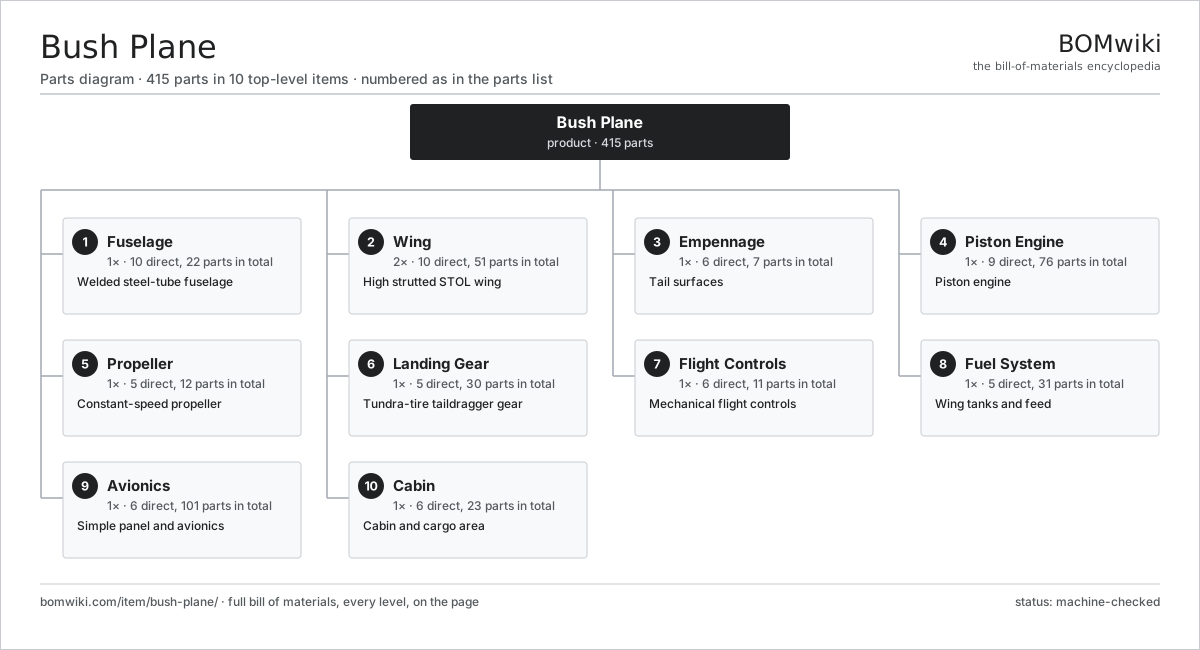
| # | Part | Qty | What it does |
|---|---|---|---|
| 1 | Fuselage 10 parts | 1× | Welded steel-tube fuselage |
| 2 | Wing 10 parts | 2× | High strutted STOL wing |
| 3 | Empennage 6 parts | 1× | Tail surfaces |
| 4 | Piston Engine 9 parts | 1× | Piston engine |
| 5 | Propeller 5 parts | 1× | Constant-speed propeller |
| 6 | Landing Gear 5 parts | 1× | Tundra-tire taildragger gear |
| 7 | Flight Controls 6 parts | 1× | Mechanical flight controls |
| 8 | Fuel System 5 parts | 1× | Wing tanks and feed |
| 9 | Avionics 6 parts | 1× | Simple panel and avionics |
| 10 | Cabin 6 parts | 1× | Cabin and cargo area |
3D model
No 3D model yet. Have a CAD file of this? Add a 3D model. STL renders right on this page; STEP, FreeCAD, and OpenSCAD sources are welcome too (openly licensed, like all 3D models on BOMwiki).
Build & assembly graph
expand / collapse · shared sub-assemblies converge · links to related products · est. labourTap an assembly to expand/collapse · tap a part to open it · use “Open page” for any node · drag to pan, scroll to zoom.
Bill of materials for Bush Plane
10 top-level lines · 148 rows shown · 415 parts total · indented to 3 levels| # | Item / sub-assembly | Part no. | Qty/assy | Ext. qty | Parts | Type |
|---|---|---|---|---|---|---|
| 1 | Fuselage 10 parts | bush-plane-fuselage | 1× | 1 | 22 | assembly |
| 1.1 | Tube Truss | bush-plane-tube-truss | 1× | 1 | · | part |
| 1.2 | Engine Mount 2 parts | bush-plane-engine-mount | 1× | 1 | 5 | assembly |
| 1.2.1 | Mount Frame | bush-plane-mount-frame | 1× | 1 | · | part |
| 1.2.2 | Mount Isolator | bush-plane-mount-isolator | 4× | 4 | · | part |
| 1.3 | Firewall | bush-plane-firewall | 1× | 1 | · | part |
| 1.4 | Fabric Covering | bush-plane-fabric-cover | 1× | 1 | · | part |
| 1.5 | Belly Skin | bush-plane-belly-skin | 1× | 1 | · | part |
| 1.6 | Cabin Door 3 parts | bush-plane-cabin-door | 2× | 2 | 3 | assembly |
| 1.6.1 | Door Frame | bush-plane-door-frame | 1× | 2 | · | part |
| 1.6.2 | Door Latch | bush-plane-door-latch | 1× | 2 | · | part |
| 1.6.3 | Side Window | bush-plane-side-window | 1× | 2 | · | part |
| 1.7 | Cargo Door | bush-plane-cargo-door | 1× | 1 | · | part |
| 1.8 | Windshield | bush-plane-windshield | 1× | 1 | · | part |
| 1.9 | Side Window | bush-plane-side-window | 4× | 4 | · | part |
| 1.10 | Fastener Set | fastener-set | 1× | 1 | · | part |
| 2 | Wing 10 parts | bush-plane-wing | 2× | 2 | 51 | assembly |
| 2.1 | Wing Spar | bush-plane-wing-spar | 2× | 4 | · | part |
| 2.2 | Wing Rib | bush-plane-wing-rib | 14× | 28 | · | part |
| 2.3 | Wing Skin | bush-plane-wing-skin | 4× | 8 | · | part |
| 2.4 | Wing Fabric | bush-plane-wing-fabric | 1× | 2 | · | part |
| 2.5 | Lift Strut | bush-plane-lift-strut | 1× | 2 | · | part |
| 2.6 | Leading-Edge Slat | bush-plane-leading-edge-slat | 1× | 2 | · | part |
| 2.7 | Aileron | bush-plane-aileron | 1× | 2 | · | part |
| 2.8 | Flap 3 parts | bush-plane-flap | 1× | 2 | 6 | assembly |
| 2.8.1 | Flap Panel | bush-plane-flap-panel | 1× | 2 | · | part |
| 2.8.2 | Flap Hinge | bush-plane-flap-hinge | 3× | 6 | · | part |
| 2.8.3 | Flap Track | bush-plane-flap-track | 2× | 4 | · | part |
| 2.9 | Wing Tip | bush-plane-wing-tip | 1× | 2 | · | part |
| 2.10 | Vortex Generator | bush-plane-vortex-generator | 20× | 40 | · | part |
| 3 | Empennage 6 parts | bush-plane-empennage | 1× | 1 | 7 | assembly |
| 3.1 | Vertical Fin | bush-plane-vertical-fin | 1× | 1 | · | part |
| 3.2 | Rudder | bush-plane-rudder | 1× | 1 | · | part |
| 3.3 | Horizontal Stabiliser | bush-plane-horizontal-stab | 1× | 1 | · | part |
| 3.4 | Elevator | bush-plane-elevator | 1× | 1 | · | part |
| 3.5 | Trim Tab | bush-plane-trim-tab | 1× | 1 | · | part |
| 3.6 | Tail Brace Wire | bush-plane-tail-brace | 2× | 2 | · | part |
| 4 | Piston Engine 9 parts | bush-plane-powerplant | 1× | 1 | 76 | assembly |
| 4.1 | Crankcase | bush-plane-crankcase | 1× | 1 | · | part |
| 4.2 | Crankshaft 3 parts | bush-plane-crankshaft | 1× | 1 | 11 | assembly |
| 4.2.1 | Crankshaft Forging | bush-plane-crank-forging | 1× | 1 | · | part |
| 4.2.2 | Connecting Rod | bush-plane-conrod | 6× | 6 | · | part |
| 4.2.3 | Main Bearing | bush-plane-main-bearing | 4× | 4 | · | part |
| 4.3 | Cylinder 4 parts | bush-plane-cylinder | 6× | 6 | 6 | assembly |
| 4.3.1 | Cylinder Barrel | bush-plane-cylinder-barrel | 1× | 6 | · | part |
| 4.3.2 | Cylinder Head | bush-plane-cylinder-head | 1× | 6 | · | part |
| 4.3.3 | Valve | bush-plane-valve | 2× | 12 | · | part |
| 4.3.4 | Spark Plug | bush-plane-spark-plug | 2× | 12 | · | part |
| 4.4 | Piston | bush-plane-piston | 6× | 6 | · | part |
| 4.5 | Camshaft | bush-plane-camshaft | 1× | 1 | · | part |
| 4.6 | Magneto 3 parts | bush-plane-magneto | 2× | 2 | 3 | assembly |
| 4.6.1 | Magneto Rotor | bush-plane-magneto-rotor | 1× | 2 | · | part |
| 4.6.2 | Magneto Coil | bush-plane-magneto-coil | 1× | 2 | · | part |
| 4.6.3 | Distributor | bush-plane-distributor | 1× | 2 | · | part |
| 4.7 | Carburetor 3 parts | bush-plane-carburetor | 1× | 1 | 3 | assembly |
| 4.7.1 | Carburetor Float | bush-plane-carb-float | 1× | 1 | · | part |
| 4.7.2 | Carburetor Jet | bush-plane-carb-jet | 1× | 1 | · | part |
| 4.7.3 | Throttle Valve | bush-plane-throttle-valve | 1× | 1 | · | part |
| 4.8 | Oil System 3 parts | bush-plane-oil-system | 1× | 1 | 4 | assembly |
| 4.8.1 | Oil Pump 2 parts + deeper › | bush-plane-oil-pump | 1× | 1 | 2 | assembly |
| 4.8.2 | Oil Cooler | bush-plane-oil-cooler | 1× | 1 | · | part |
| 4.8.3 | Oil Filter | bush-plane-oil-filter | 1× | 1 | · | part |
| 4.9 | Exhaust System 3 parts | bush-plane-exhaust | 1× | 1 | 8 | assembly |
| 4.9.1 | Exhaust Stack | bush-plane-exhaust-stack | 6× | 6 | · | part |
| 4.9.2 | Muffler | bush-plane-muffler | 1× | 1 | · | part |
| 4.9.3 | Heat Shroud | bush-plane-heat-shroud | 1× | 1 | · | part |
| 5 | Propeller 5 parts | bush-plane-propeller | 1× | 1 | 12 | assembly |
| 5.1 | Propeller Blade | bush-plane-prop-blade | 3× | 3 | · | part |
| 5.2 | Propeller Hub | bush-plane-prop-hub | 1× | 1 | · | part |
| 5.3 | Pitch-Change Actuator 3 parts | bush-plane-pitch-actuator | 1× | 1 | 3 | assembly |
| 5.3.1 | Pitch Piston | bush-plane-pitch-piston | 1× | 1 | · | part |
| 5.3.2 | Coil Spring | coil-spring | 1× | 1 | · | part |
| 5.3.3 | O-Ring Set | oring-set | 1× | 1 | · | part |
| 5.4 | Propeller Governor 3 parts | bush-plane-prop-governor | 1× | 1 | 4 | assembly |
| 5.4.1 | Helical Gear Pair | gear-pair | 1× | 1 | · | part |
| 5.4.2 | Governor Flyweight | bush-plane-flyweight | 2× | 2 | · | part |
| 5.4.3 | Coil Spring | coil-spring | 1× | 1 | · | part |
| 5.5 | Spinner | bush-plane-spinner | 1× | 1 | · | part |
| 6 | Landing Gear 5 parts | bush-plane-landing-gear | 1× | 1 | 30 | assembly |
| 6.1 | Main Gear Leg 4 parts | bush-plane-main-gear | 2× | 2 | 4 | assembly |
| 6.1.1 | Gear Leg | bush-plane-gear-leg | 1× | 2 | · | part |
| 6.1.2 | Shock Absorber | bush-plane-shock-absorber | 1× | 2 | · | part |
| 6.1.3 | Wheel | bush-plane-wheel | 1× | 2 | · | part |
| 6.1.4 | Tundra Tire | bush-plane-tundra-tire | 1× | 2 | · | part |
| 6.2 | Tailwheel 3 parts | bush-plane-tailwheel | 1× | 1 | 4 | assembly |
| 6.2.1 | Tailwheel Fork | bush-plane-tailwheel-fork | 1× | 1 | · | part |
| 6.2.2 | Tailwheel Tire | bush-plane-tailwheel-tire | 1× | 1 | · | part |
| 6.2.3 | Coil Spring | coil-spring | 2× | 2 | · | part |
| 6.3 | Brake Assembly 3 parts | bush-plane-brake-assembly | 2× | 2 | 3 | assembly |
| 6.3.1 | Brake Disc | bush-plane-brake-disc | 1× | 2 | · | part |
| 6.3.2 | Brake Caliper | bush-plane-brake-caliper | 1× | 2 | · | part |
| 6.3.3 | O-Ring Set | oring-set | 1× | 2 | · | part |
| 6.4 | Float Kit 3 parts | bush-plane-float-kit | 1× | 1 | 8 | assembly |
| 6.4.1 | Float Hull | bush-plane-float-hull | 2× | 2 | · | part |
| 6.4.2 | Water Rudder | bush-plane-water-rudder | 2× | 2 | · | part |
| 6.4.3 | Float Strut | bush-plane-float-strut | 4× | 4 | · | part |
| 6.5 | Ski Kit 2 parts | bush-plane-ski-kit | 1× | 1 | 4 | assembly |
| 6.5.1 | Ski | bush-plane-ski | 2× | 2 | · | part |
| 6.5.2 | Ski Pedestal | bush-plane-ski-pedestal | 2× | 2 | · | part |
| 7 | Flight Controls 6 parts | bush-plane-flight-controls | 1× | 1 | 11 | assembly |
| 7.1 | Control Stick | bush-plane-control-stick | 2× | 2 | · | part |
| 7.2 | Rudder Pedal Set | bush-plane-rudder-pedal | 2× | 2 | · | part |
| 7.3 | Control Cable Run | bush-plane-control-cable | 1× | 1 | · | part |
| 7.4 | Push-Rod | bush-plane-push-rod | 4× | 4 | · | part |
| 7.5 | Flap Lever | bush-plane-flap-lever | 1× | 1 | · | part |
| 7.6 | Trim Wheel | bush-plane-trim-wheel | 1× | 1 | · | part |
| 8 | Fuel System 5 parts | bush-plane-fuel-system | 1× | 1 | 31 | assembly |
| 8.1 | Fuel Tank | bush-plane-fuel-tank | 2× | 2 | · | part |
| 8.2 | Fuel Selector | bush-plane-fuel-selector | 1× | 1 | · | part |
| 8.3 | Fuel Boost Pump 2 parts | bush-plane-fuel-pump | 1× | 1 | 25 | assembly |
| 8.3.1 | Servo Motor 4 parts + deeper › | servo-motor | 1× | 1 | 24 | assembly |
| 8.3.2 | Oil Seal | oil-seal | 1× | 1 | · | part |
| 8.4 | Gascolator | bush-plane-gascolator | 1× | 1 | · | part |
| 8.5 | Fuel Quantity Sender | bush-plane-fuel-gauge | 2× | 2 | · | part |
| 9 | Avionics 6 parts | bush-plane-avionics | 1× | 1 | 101 | assembly |
| 9.1 | EFIS Display 4 parts | bush-plane-efis-display | 1× | 1 | 7 | assembly |
| 9.1.1 | LCD Panel | lcd-panel | 1× | 1 | · | part |
| 9.1.2 | Bare PCB | pcb-bare | 1× | 1 | · | part |
| 9.1.3 | Microcontroller | mcu | 1× | 1 | · | part |
| 9.1.4 | Connector | connector | 4× | 4 | · | part |
| 9.2 | VHF Radio 3 parts | bush-plane-vhf-radio | 1× | 1 | 4 | assembly |
| 9.2.1 | Bare PCB | pcb-bare | 1× | 1 | · | part |
| 9.2.2 | Microcontroller | mcu | 1× | 1 | · | part |
| 9.2.3 | Connector | connector | 2× | 2 | · | part |
| 9.3 | GPS Navigator 3 parts | bush-plane-gps | 1× | 1 | 82 | assembly |
| 9.3.1 | Bare PCB | pcb-bare | 1× | 1 | · | part |
| 9.3.2 | Microcontroller | mcu | 1× | 1 | · | part |
| 9.3.3 | SMD Passive (R/C/L) | smd-passives | 80× | 80 | · | part |
| 9.4 | Transponder 3 parts | bush-plane-transponder | 1× | 1 | 4 | assembly |
| 9.4.1 | Bare PCB | pcb-bare | 1× | 1 | · | part |
| 9.4.2 | Microcontroller | mcu | 1× | 1 | · | part |
| 9.4.3 | Connector | connector | 2× | 2 | · | part |
| 9.5 | Emergency Locator Transmitter 3 parts | bush-plane-elt | 1× | 1 | 3 | assembly |
| 9.5.1 | Bare PCB | pcb-bare | 1× | 1 | · | part |
| 9.5.2 | Microcontroller | mcu | 1× | 1 | · | part |
| 9.5.3 | ELT Battery | bush-plane-elt-battery | 1× | 1 | · | part |
| 9.6 | Magnetic Compass | bush-plane-magnetic-compass | 1× | 1 | · | part |
| 10 | Cabin 6 parts | bush-plane-cabin | 1× | 1 | 23 | assembly |
| 10.1 | Seat 2 parts | bush-plane-seat | 2× | 2 | 2 | assembly |
| 10.1.1 | Seat Frame | bush-plane-seat-frame | 1× | 2 | · | part |
| 10.1.2 | Seat Cushion | bush-plane-seat-cushion | 1× | 2 | · | part |
| 10.2 | Seatbelt | bush-plane-seatbelt | 4× | 4 | · | part |
| 10.3 | Cargo Floor | bush-plane-cargo-floor | 1× | 1 | · | part |
| 10.4 | Cargo Tie-Down | bush-plane-tie-down | 6× | 6 | · | part |
| 10.5 | Cabin Heater 2 parts | bush-plane-cabin-heater | 1× | 1 | 2 | assembly |
| 10.5.1 | Heat Valve | bush-plane-heat-valve | 1× | 1 | · | part |
| 10.5.2 | Heat Duct | bush-plane-heat-duct | 1× | 1 | · | part |
| 10.6 | Interior Panel | bush-plane-interior-panel | 6× | 6 | · | part |
Related products
same domain, ranked by shared parts Floatplane
813 parts · shares 16 with this page
Floatplane
813 parts · shares 16 with this page
 Flying Boat
4,224 parts · shares 16 with this page
Flying Boat
4,224 parts · shares 16 with this page
 Freighter Aircraft
6,717 parts · shares 16 with this page
Freighter Aircraft
6,717 parts · shares 16 with this page
 Turboprop Airliner
3,298 parts · shares 16 with this page
Turboprop Airliner
3,298 parts · shares 16 with this page
 Gyroplane
168 parts · shares 15 with this page
Heavy-Lift Helicopter
1,794 parts · shares 15 with this page
Gyroplane
168 parts · shares 15 with this page
Heavy-Lift Helicopter
1,794 parts · shares 15 with this page
Sourcing: possible vendors
Browse the supplier directory → Prices, MOQ, and lead times are algorithmic estimates, not quotes, and not claims about these companies. Company mappings are curated by keyword; est. price band $50k–$300M. How estimates work| Vendor | HQ | Specialty | MOQ | Lead time |
|---|---|---|---|---|
|
🇺🇸Boeing
boeing.com ↗
|
Arlington, US | Aerospace OEM | made to order | 40–80 wks |
|
🇫🇷Airbus
airbus.com ↗
|
Toulouse, FR | Aerospace OEM | made to order | 40–80 wks |
| lockheedmartin.com ↗ | Bethesda, US | Aerospace & defense | made to order | 40–80 wks |
|
🇧🇷Embraer
embraer.com ↗
|
São José dos Campos, BR | Aircraft OEM | made to order | 40–80 wks |
| txtav.com ↗ | Wichita, US | Aircraft OEM | made to order | 40–80 wks |
1,165-word article