Agricultural Helicopter
ProductOverview
An agricultural helicopter is a light turbine helicopter fitted out for aerial application: spraying pesticide, fungicide, or liquid fertiliser, and sometimes spreading dry product over crops. The helicopter is chosen over a fixed-wing agricultural aircraft where the fields are small, irregular, terraced, or boxed in by trees and power lines, because it can fly slow, turn tight, and operate from a truck or a clearing without a runway. Its rotor downwash also helps drive spray down into the canopy and onto the underside of leaves, improving coverage.
The aircraft is a conventional helicopter, a Airframe carrying a Main Rotor System, a Tail Rotor, and a Powertrain, with the agricultural identity coming from the Spray System bolted to it and the Avionics & Guidance guidance that makes precise application possible.
Airframe
The Airframe starts with a welded Cabin Frame in 4130 steel that carries the rotor, engine, and spray loads, with an aluminium monocoque Tailboom running the tail rotor drive aft. A large acrylic Canopy gives the pilot the wide downward view needed to fly low along crop rows, and a stainless Firewall isolates the engine. The Vertical Fin offloads the tail rotor in forward flight, and the Horizontal Stabiliser trims pitch, with Sheet Metal Panel skins closing out the structure.
Rotor systems
The Main Rotor System produces both lift and control. A Rotor Head carries the Main Rotor Blade pair and lets them flap and feather, while a Swashplate turns the pilot fixed-frame inputs into rotating blade pitch through Pitch Link rods. The Rotor Mast carries torque and thrust into the airframe, and Lead-Lag Damper units control in-plane blade motion, all running on Ball Bearing supports. Because a single main rotor would spin the fuselage the other way, the Tail Rotor counters that torque and gives yaw control. Its Tail Rotor Blade pair on a Tail Rotor Hub is driven through a Tail Driveshaft and a right-angle Tail Gearbox, with pedal inputs reaching the blades through a Pitch Slider and a Helical Gear Pair.
Powertrain
The Powertrain is usually a Turboshaft Engine turboshaft of 250 to 450 kW, chosen for its power-to-weight and its tolerance of the hot, dusty, repetitive duty of agricultural work. Inlet air is raised in pressure by the Compressor, burned in the Combustor, and expanded through the Turbine to drive the rotor shaft, with a Engine Control Unit governing fuel and rotor rpm. The Main Gearbox reduces engine speed to rotor speed, a Freewheel Clutch sprag unit lets the rotor autorotate if the engine quits, and a crash-resistant Fuel Tank plus a Oil Cooler complete the system.
Spray system
The Spray System is what turns a helicopter into an applicator. Two Chemical Tank hoppers flank the cabin to keep the load near the centre of gravity, kept mixed by a Tank Agitator. A Spray Pump, wind-driven or hydraulic, pressurises the circuit and feeds two Spray Boom arms that span the rotor wash. Around 40 Spray Nozzle tips atomise the liquid to a controlled droplet size, large enough to resist drift, fine enough to coat the leaf. A Flow Control Valve valve meters the application rate against ground speed so the dose stays even, and a Quick-Dump Valve valve sheds the load fast in an emergency. Pressure Sensor elements monitor line pressure to flag a blocked or leaking boom.
Landing gear, guidance and use
High Landing Gear skids give the booms ground clearance and a stable base for repeated loading. Two Skid Tube runners on arched Cross Tube members carry replaceable Skid Shoe wear pads, and removable Ground Handling Wheel units allow towing. Precision comes from the Avionics & Guidance: a GPS Guidance system computes each swath so passes abut without gaps or double-dosing, and a Steering Lightbar steers the pilot onto the next line, with a Flight Display and a Radio rounding out the cockpit on a Bare PCB, Microcontroller, and Power Supply backbone. These aircraft fly crop protection, aerial seeding, and fertiliser spreading, valued for tight-field access and the downwash that improves canopy penetration, while their operators work under strict rules on drift, buffer zones, and chemical handling.
Operation and economics
An agricultural helicopter earns its keep by turnaround time, not by hopper size. A loaded machine sprays its Chemical Tank hoppers dry in a few minutes, so the operation lives or dies on how fast the ground crew can refill chemical and fuel between passes. Many outfits run a nurse truck at the field edge so the helicopter never shuts down between loads, hot-loading through the Spray Pump circuit while the rotor turns. Spray quality is the other half of the job. The Spray Nozzle tips are matched to the chemical label and the wind so droplets are large enough to fall onto the target rather than drift onto a neighbouring field, and the Flow Control Valve valve trims the rate against ground speed read from the GPS Guidance so a slow pass over an obstacle does not over-apply. Pilots fly long days at low level near wires, trees, and rising ground, which is the most demanding part of the work and the reason these aircraft carry wire-strike protection and the pilot trains specifically for the low, repetitive flight pattern. Maintenance is heavy because the dusty, chemical environment is hard on the Turboshaft Engine inlet and the rotor bearings, so daily washdowns and frequent inspections are routine.
Agricultural Helicopter parts and their functions
7 top-level parts · 133 parts in total · full bill of materials below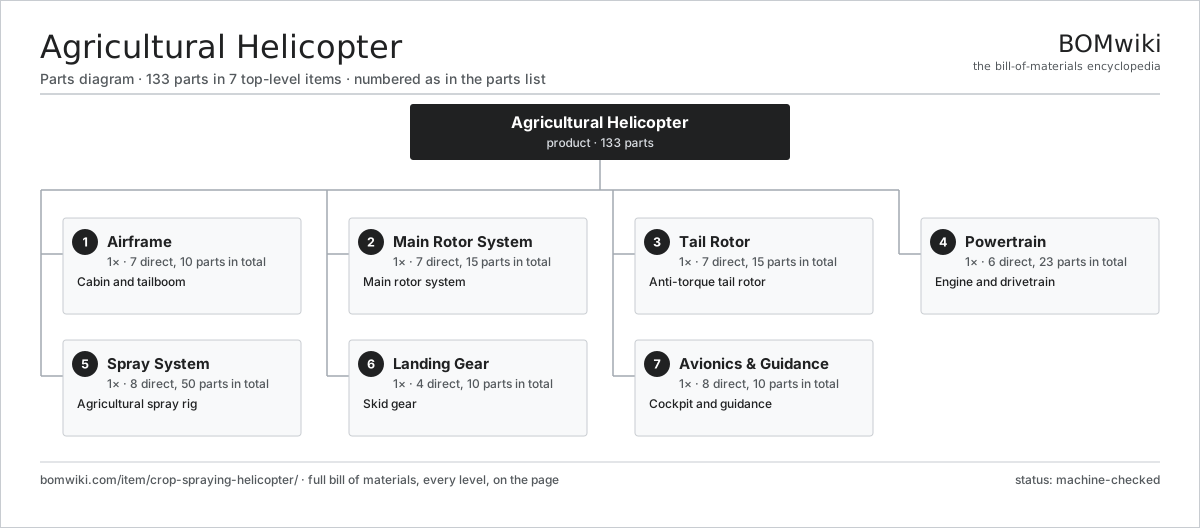
| # | Part | Qty | What it does |
|---|---|---|---|
| 1 | Airframe 7 parts | 1× | Cabin and tailboom |
| 2 | Main Rotor System 7 parts | 1× | Main rotor system |
| 3 | Tail Rotor 7 parts | 1× | Anti-torque tail rotor |
| 4 | Powertrain 6 parts | 1× | Engine and drivetrain |
| 5 | Spray System 8 parts | 1× | Agricultural spray rig |
| 6 | Landing Gear 4 parts | 1× | Skid gear |
| 7 | Avionics & Guidance 8 parts | 1× | Cockpit and guidance |
3D model
No 3D model yet. Have a CAD file of this? Add a 3D model. STL renders right on this page; STEP, FreeCAD, and OpenSCAD sources are welcome too (openly licensed, like all 3D models on BOMwiki).
Build & assembly graph
expand / collapse · shared sub-assemblies converge · links to related products · est. labourTap an assembly to expand/collapse · tap a part to open it · use “Open page” for any node · drag to pan, scroll to zoom.
Bill of materials for Agricultural Helicopter
7 top-level lines · 68 rows shown · 133 parts total · indented to 3 levels| # | Item / sub-assembly | Part no. | Qty/assy | Ext. qty | Parts | Type |
|---|---|---|---|---|---|---|
| 1 | Airframe 7 parts | crop-spraying-helicopter-airframe | 1× | 1 | 10 | assembly |
| 1.1 | Cabin Frame | crop-spraying-helicopter-cabin-frame | 1× | 1 | · | part |
| 1.2 | Tailboom | crop-spraying-helicopter-tailboom | 1× | 1 | · | part |
| 1.3 | Canopy | crop-spraying-helicopter-canopy | 1× | 1 | · | part |
| 1.4 | Firewall | crop-spraying-helicopter-firewall | 1× | 1 | · | part |
| 1.5 | Vertical Fin | crop-spraying-helicopter-vertical-fin | 1× | 1 | · | part |
| 1.6 | Horizontal Stabiliser | crop-spraying-helicopter-horizontal-stab | 1× | 1 | · | part |
| 1.7 | Sheet Metal Panel | sheet-panel | 4× | 4 | · | part |
| 2 | Main Rotor System 7 parts | crop-spraying-helicopter-main-rotor | 1× | 1 | 15 | assembly |
| 2.1 | Rotor Head | crop-spraying-helicopter-rotor-head | 1× | 1 | · | part |
| 2.2 | Main Rotor Blade | crop-spraying-helicopter-main-blade | 2× | 2 | · | part |
| 2.3 | Swashplate | crop-spraying-helicopter-swashplate | 1× | 1 | · | part |
| 2.4 | Pitch Link | crop-spraying-helicopter-pitch-link | 2× | 2 | · | part |
| 2.5 | Rotor Mast | crop-spraying-helicopter-mast | 1× | 1 | · | part |
| 2.6 | Lead-Lag Damper | crop-spraying-helicopter-damper | 2× | 2 | · | part |
| 2.7 | Ball Bearing | ball-bearing | 6× | 6 | · | part |
| 3 | Tail Rotor 7 parts | crop-spraying-helicopter-tail-rotor | 1× | 1 | 15 | assembly |
| 3.1 | Tail Rotor Blade | crop-spraying-helicopter-tail-blade | 2× | 2 | · | part |
| 3.2 | Tail Rotor Hub | crop-spraying-helicopter-tail-hub | 1× | 1 | · | part |
| 3.3 | Tail Gearbox 4 parts | crop-spraying-helicopter-tail-gearbox | 1× | 1 | 5 | assembly |
| 3.3.1 | Helical Gear Pair | gear-pair | 1× | 1 | · | part |
| 3.3.2 | Gearbox Housing | gearbox-housing | 1× | 1 | · | part |
| 3.3.3 | Ball Bearing | ball-bearing | 2× | 2 | · | part |
| 3.3.4 | Oil Seal | oil-seal | 1× | 1 | · | part |
| 3.4 | Tail Driveshaft | crop-spraying-helicopter-tail-driveshaft | 1× | 1 | · | part |
| 3.5 | Pitch Slider | crop-spraying-helicopter-pitch-slider | 1× | 1 | · | part |
| 3.6 | Helical Gear Pair | gear-pair | 1× | 1 | · | part |
| 3.7 | Ball Bearing | ball-bearing | 4× | 4 | · | part |
| 4 | Powertrain 6 parts | crop-spraying-helicopter-powertrain | 1× | 1 | 23 | assembly |
| 4.1 | Turboshaft Engine 6 parts | crop-spraying-helicopter-engine | 1× | 1 | 10 | assembly |
| 4.1.1 | Compressor | crop-spraying-helicopter-compressor | 1× | 1 | · | part |
| 4.1.2 | Combustor | crop-spraying-helicopter-combustor | 1× | 1 | · | part |
| 4.1.3 | Turbine | crop-spraying-helicopter-turbine | 1× | 1 | · | part |
| 4.1.4 | Engine Control Unit | crop-spraying-helicopter-fadec | 1× | 1 | · | part |
| 4.1.5 | Ball Bearing | ball-bearing | 4× | 4 | · | part |
| 4.1.6 | Oil Seal | oil-seal | 2× | 2 | · | part |
| 4.2 | Main Gearbox 4 parts | crop-spraying-helicopter-main-gearbox | 1× | 1 | 9 | assembly |
| 4.2.1 | Helical Gear Pair | gear-pair | 2× | 2 | · | part |
| 4.2.2 | Gearbox Housing | gearbox-housing | 1× | 1 | · | part |
| 4.2.3 | Ball Bearing | ball-bearing | 4× | 4 | · | part |
| 4.2.4 | Oil Seal | oil-seal | 2× | 2 | · | part |
| 4.3 | Freewheel Clutch | crop-spraying-helicopter-clutch | 1× | 1 | · | part |
| 4.4 | Fuel Tank | crop-spraying-helicopter-fuel-tank | 1× | 1 | · | part |
| 4.5 | Oil Cooler | crop-spraying-helicopter-oil-cooler | 1× | 1 | · | part |
| 4.6 | Drive Belt | drive-belt | 1× | 1 | · | part |
| 5 | Spray System 8 parts | crop-spraying-helicopter-spray-system | 1× | 1 | 50 | assembly |
| 5.1 | Chemical Tank | crop-spraying-helicopter-chemical-tank | 2× | 2 | · | part |
| 5.2 | Spray Pump | crop-spraying-helicopter-spray-pump | 1× | 1 | · | part |
| 5.3 | Spray Boom | crop-spraying-helicopter-spray-boom | 2× | 2 | · | part |
| 5.4 | Spray Nozzle | crop-spraying-helicopter-nozzle | 40× | 40 | · | part |
| 5.5 | Flow Control Valve | crop-spraying-helicopter-flow-control | 1× | 1 | · | part |
| 5.6 | Quick-Dump Valve | crop-spraying-helicopter-quick-dump | 1× | 1 | · | part |
| 5.7 | Tank Agitator | crop-spraying-helicopter-agitator | 1× | 1 | · | part |
| 5.8 | Pressure Sensor | pressure-sensor | 2× | 2 | · | part |
| 6 | Landing Gear 4 parts | crop-spraying-helicopter-landing-gear | 1× | 1 | 10 | assembly |
| 6.1 | Skid Tube | crop-spraying-helicopter-skid-tube | 2× | 2 | · | part |
| 6.2 | Cross Tube | crop-spraying-helicopter-cross-tube | 2× | 2 | · | part |
| 6.3 | Skid Shoe | crop-spraying-helicopter-skid-shoe | 4× | 4 | · | part |
| 6.4 | Ground Handling Wheel | crop-spraying-helicopter-ground-handling-wheel | 2× | 2 | · | part |
| 7 | Avionics & Guidance 8 parts | crop-spraying-helicopter-avionics | 1× | 1 | 10 | assembly |
| 7.1 | Flight Display | crop-spraying-helicopter-flight-display | 1× | 1 | · | part |
| 7.2 | GPS Guidance | crop-spraying-helicopter-gps-guidance | 1× | 1 | · | part |
| 7.3 | Steering Lightbar | crop-spraying-helicopter-lightbar | 1× | 1 | · | part |
| 7.4 | Radio | crop-spraying-helicopter-radio | 1× | 1 | · | part |
| 7.5 | Bare PCB | pcb-bare | 2× | 2 | · | part |
| 7.6 | Microcontroller | mcu | 2× | 2 | · | part |
| 7.7 | Power Supply | power-supply | 1× | 1 | · | part |
| 7.8 | Wire Bundle | wire-bundle | 1× | 1 | · | part |
Related products
same domain, ranked by shared parts Floatplane
813 parts · shares 4 with this page
Floatplane
813 parts · shares 4 with this page
 Agricultural Aircraft
233 parts · shares 4 with this page
Agricultural Aircraft
233 parts · shares 4 with this page
 Aircraft APU
106 parts · shares 4 with this page
Aircraft APU
106 parts · shares 4 with this page
 Amphibious Seaplane
163 parts · shares 4 with this page
Amphibious Seaplane
163 parts · shares 4 with this page
 Jet Trainer Aircraft
319 parts · shares 4 with this page
Jet Trainer Aircraft
319 parts · shares 4 with this page
 Flying Boat
4,224 parts · shares 4 with this page
Flying Boat
4,224 parts · shares 4 with this page
Sourcing: possible vendors
Browse the supplier directory → Prices, MOQ, and lead times are algorithmic estimates, not quotes, and not claims about these companies. Company mappings are curated by keyword; est. price band $50k–$300M. How estimates work| Vendor | HQ | Specialty | MOQ | Lead time |
|---|---|---|---|---|
|
🇺🇸Boeing
boeing.com ↗
|
Arlington, US | Aerospace OEM | made to order | 40–80 wks |
|
🇫🇷Airbus
airbus.com ↗
|
Toulouse, FR | Aerospace OEM | made to order | 40–80 wks |
| lockheedmartin.com ↗ | Bethesda, US | Aerospace & defense | made to order | 40–80 wks |
|
🇧🇷Embraer
embraer.com ↗
|
São José dos Campos, BR | Aircraft OEM | made to order | 40–80 wks |
| txtav.com ↗ | Wichita, US | Aircraft OEM | made to order | 40–80 wks |
1,063-word article