Glider
ProductOverview
The Glider is a single-seat high-performance sailplane built to stay airborne for hours and to cross hundreds of kilometres without an engine. It carries no powerplant and no fuel of any kind. Once it is off the ground it climbs only by finding air that is rising faster than the glider sinks through it, and it converts the height it gains into distance by gliding at a very flat angle. Everything about the airframe serves those two needs: a Wing of very high aspect ratio to glide far, and a clean, light, low-drag shape so that the sink rate in still air stays small.
The aircraft is built around a slender composite Fuselage pod and boom, an 18 metre Wing in two panels, and a Empennage T-tail. A retractable Landing Gear monowheel carries it on the ground. Direct mechanical Flight Controls move the surfaces, a Release System connects the launch cable, and a Water Ballast System system lets the pilot tune the weight to the strength of the day.
Aerodynamics
The whole point of a sailplane is a high lift-to-drag ratio. At its best glide speed of about 110 km/h this design loses roughly one metre of height for every 52 metres it travels, a glide ratio of 52:1. That number comes from the Wing: an aspect ratio near 28 means the wing is long and very narrow, which cuts the induced drag that trails off the tips when a wing makes lift. A Winglet at each tip cuts that tip loss further. The Wing Skin is a carbon-foam sandwich moulded and finished so the surface stays smooth and the airflow stays laminar over much of the chord, which keeps the friction drag low. The minimum sink rate, about 0.45 m/s, is the slowest the glider falls through still air, and it sets how weak a patch of rising air still has to be to keep the glider up.
The structure that makes the thin wing possible is the Wing Spar, a carbon box spar whose Spar Cap flanges carry the bending load and whose Spar Web carries the shear. The spar roots of the two panels lock together inside the Main Frame with steel Wing Pin pins, so the wing acts as one continuous beam across the fuselage.
Soaring
A glider gains height in three kinds of rising air. Thermals are columns of warm air drifting up off ground that the sun has heated, and the pilot circles tightly inside one to ride it up before gliding off to find the next. Ridge lift forms where wind strikes a hill and is forced upward along the slope, letting a glider beat back and forth in front of the ridge for as long as the wind blows. Wave lift forms downwind of a mountain range, where the airflow sets up smooth standing waves that can reach into the stratosphere. The instrument that tells the pilot which kind of air they are in is the Variometer, a total-energy variometer that reads the Pressure Sensor difference and shows whether the air itself is going up or down rather than just whether the glider is climbing. A Flight Computer adds GPS navigation, draws the task, and works out the final glide home so the pilot knows from far out whether they can reach the airfield without another climb.
Water Ballast
The Water Ballast System system is how the pilot matches the glider to the weather. The Ballast Tank bladders in the wings hold up to about 200 litres of water. Adding water raises the wing loading from roughly 35 to over 50 kg/m2. A heavier glider flies faster at the same glide angle, so on a strong day with powerful thermals the extra speed between climbs wins more distance than the slightly worse climb rate costs. When the lift weakens, the pilot opens the Dump Valve valves and drops the water in under a minute, going back to the light, slow-flying configuration that climbs best in weak air. A small Tail Ballast Tank tank in the fin trims the balance so the centre of gravity stays correct as the wing water comes and goes. The water is always dumped before landing so the glider touches down light.
Airbrakes and Landing
A glider that glides 52:1 is hard to bring down on a fixed runway, because it does not want to lose height. The answer is the Airbrake, a pair of Airbrake Panel blades that rise out of the upper wing surface on a Airbrake Linkage and deliberately spoil the lift and add drag. With the airbrakes fully out the glide angle steepens sharply, so the pilot can aim well into the field and then control the descent precisely down to the flare. Landing is onto the single sprung Monowheel, with a small Tailwheel under the boom and a Wheel Brake for the ground roll. The monowheel retracts into the fuselage in flight to cut drag.
Launch Methods
A glider needs help to get airborne, and the Release System carries two hooks for the two common methods. In an aerotow a powered tug aircraft pulls the glider up on a rope clipped to the Nose Hook at the nose, climbing together to a few thousand feet before the glider pilot pulls the Release Knob to cast off and go soaring. In a winch launch a powerful ground winch reels in a cable hooked to the CG Hook near the centre of gravity, throwing the glider steeply into the air in well under a minute to a height of a few hundred metres. The CG hook back-releases automatically as the glider passes overhead at the top of the climb. Both hooks drive the same forged Hook Body jaw through a Release Cable, and the pilot flies the whole launch on the direct Flight Controls from the reclined cockpit under the one-piece Canopy and Cockpit.
Glider parts and their functions
9 top-level parts · 337 parts in total · full bill of materials below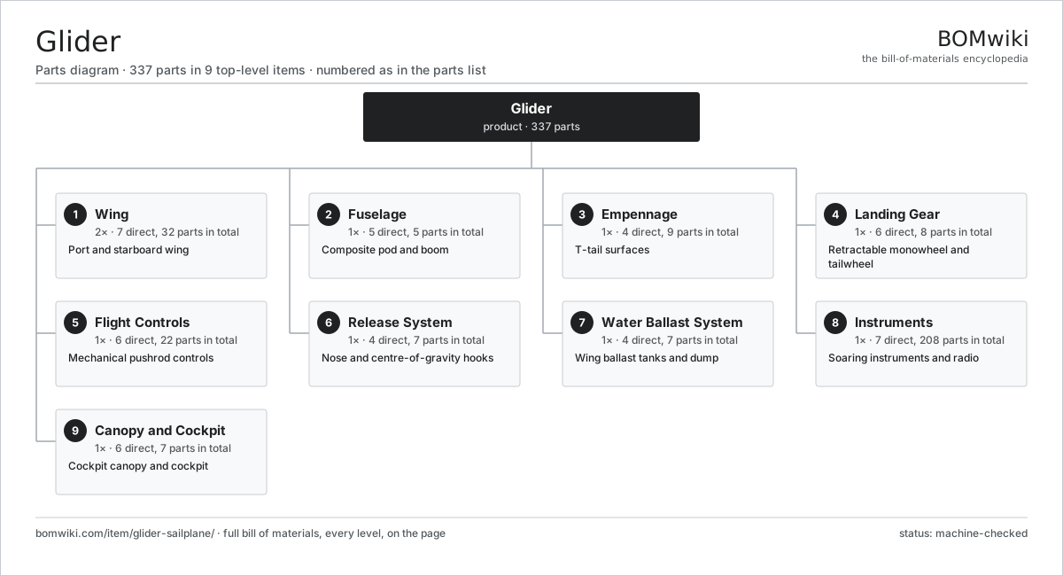
| # | Part | Qty | What it does |
|---|---|---|---|
| 1 | Wing 7 parts | 2× | Port and starboard wing |
| 2 | Fuselage 5 parts | 1× | Composite pod and boom |
| 3 | Empennage 4 parts | 1× | T-tail surfaces |
| 4 | Landing Gear 6 parts | 1× | Retractable monowheel and tailwheel |
| 5 | Flight Controls 6 parts | 1× | Mechanical pushrod controls |
| 6 | Release System 4 parts | 1× | Nose and centre-of-gravity hooks |
| 7 | Water Ballast System 4 parts | 1× | Wing ballast tanks and dump |
| 8 | Instruments 7 parts | 1× | Soaring instruments and radio |
| 9 | Canopy and Cockpit 6 parts | 1× | Cockpit canopy and cockpit |
3D model
No 3D model yet. Have a CAD file of this? Add a 3D model. STL renders right on this page; STEP, FreeCAD, and OpenSCAD sources are welcome too (openly licensed, like all 3D models on BOMwiki).
Build & assembly graph
expand / collapse · shared sub-assemblies converge · links to related products · est. labourTap an assembly to expand/collapse · tap a part to open it · use “Open page” for any node · drag to pan, scroll to zoom.
Bill of materials for Glider
9 top-level lines · 102 rows shown · 337 parts total · indented to 3 levels| # | Item / sub-assembly | Part no. | Qty/assy | Ext. qty | Parts | Type |
|---|---|---|---|---|---|---|
| 1 | Wing 7 parts | glider-sailplane-wing | 2× | 2 | 32 | assembly |
| 1.1 | Wing Spar 2 parts | glider-sailplane-wing-spar | 1× | 2 | 3 | assembly |
| 1.1.1 | Spar Cap | glider-sailplane-spar-cap | 2× | 4 | · | part |
| 1.1.2 | Spar Web | glider-sailplane-spar-web | 1× | 2 | · | part |
| 1.2 | Wing Rib | glider-sailplane-wing-rib | 14× | 28 | · | part |
| 1.3 | Wing Skin | glider-sailplane-wing-skin | 2× | 4 | · | part |
| 1.4 | Flaperon 3 parts | glider-sailplane-flaperon | 1× | 2 | 4 | assembly |
| 1.4.1 | Control Surface Skin | glider-sailplane-control-surface-skin | 1× | 2 | · | part |
| 1.4.2 | Control Horn | glider-sailplane-control-horn | 1× | 2 | · | part |
| 1.4.3 | Ball Bearing | ball-bearing | 2× | 4 | · | part |
| 1.5 | Airbrake 3 parts | glider-sailplane-airbrake | 2× | 4 | 3 | assembly |
| 1.5.1 | Airbrake Panel | glider-sailplane-airbrake-panel | 1× | 4 | · | part |
| 1.5.2 | Airbrake Linkage | glider-sailplane-airbrake-linkage | 1× | 4 | · | part |
| 1.5.3 | Coil Spring | coil-spring | 1× | 4 | · | part |
| 1.6 | Winglet | glider-sailplane-winglet | 1× | 2 | · | part |
| 1.7 | Wing Pin | glider-sailplane-wing-pin | 2× | 4 | · | part |
| 2 | Fuselage 5 parts | glider-sailplane-fuselage | 1× | 1 | 5 | assembly |
| 2.1 | Pod Shell | glider-sailplane-pod-shell | 1× | 1 | · | part |
| 2.2 | Tail Boom | glider-sailplane-tail-boom | 1× | 1 | · | part |
| 2.3 | Main Frame | glider-sailplane-main-frame | 1× | 1 | · | part |
| 2.4 | Cockpit Floor | glider-sailplane-cockpit-floor | 1× | 1 | · | part |
| 2.5 | Nose Cone | glider-sailplane-nose-cone | 1× | 1 | · | part |
| 3 | Empennage 4 parts | glider-sailplane-empennage | 1× | 1 | 9 | assembly |
| 3.1 | Vertical Fin | glider-sailplane-vertical-fin | 1× | 1 | · | part |
| 3.2 | Rudder 2 parts | glider-sailplane-rudder | 1× | 1 | 2 | assembly |
| 3.2.1 | Control Surface Skin | glider-sailplane-control-surface-skin | 1× | 1 | · | part |
| 3.2.2 | Control Horn | glider-sailplane-control-horn | 1× | 1 | · | part |
| 3.3 | All-Moving Tailplane 3 parts | glider-sailplane-stabiliser | 1× | 1 | 5 | assembly |
| 3.3.1 | Control Surface Skin | glider-sailplane-control-surface-skin | 2× | 2 | · | part |
| 3.3.2 | Control Horn | glider-sailplane-control-horn | 1× | 1 | · | part |
| 3.3.3 | Ball Bearing | ball-bearing | 2× | 2 | · | part |
| 3.4 | Tail Pin | glider-sailplane-tail-pin | 1× | 1 | · | part |
| 4 | Landing Gear 6 parts | glider-sailplane-landing-gear | 1× | 1 | 8 | assembly |
| 4.1 | Monowheel | glider-sailplane-monowheel | 1× | 1 | · | part |
| 4.2 | Gear Strut 2 parts | glider-sailplane-gear-strut | 1× | 1 | 2 | assembly |
| 4.2.1 | Strut Leg | glider-sailplane-strut-leg | 1× | 1 | · | part |
| 4.2.2 | Coil Spring | coil-spring | 1× | 1 | · | part |
| 4.3 | Retract Mechanism | glider-sailplane-retract-mechanism | 1× | 1 | · | part |
| 4.4 | Wheel Brake | glider-sailplane-wheel-brake | 1× | 1 | · | part |
| 4.5 | Tailwheel | glider-sailplane-tailwheel | 1× | 1 | · | part |
| 4.6 | Wingtip Wheel | glider-sailplane-wingtip-wheel | 2× | 2 | · | part |
| 5 | Flight Controls 6 parts | glider-sailplane-flight-controls | 1× | 1 | 22 | assembly |
| 5.1 | Control Stick | glider-sailplane-control-stick | 1× | 1 | · | part |
| 5.2 | Rudder Pedals | glider-sailplane-rudder-pedals | 1× | 1 | · | part |
| 5.3 | Pushrod | glider-sailplane-pushrod | 8× | 8 | · | part |
| 5.4 | Bellcrank | glider-sailplane-bellcrank | 6× | 6 | · | part |
| 5.5 | Auto Connector | glider-sailplane-auto-connector | 4× | 4 | · | part |
| 5.6 | Trim System 2 parts | glider-sailplane-trim-system | 1× | 1 | 2 | assembly |
| 5.6.1 | Coil Spring | coil-spring | 1× | 1 | · | part |
| 5.6.2 | Trim Lever | glider-sailplane-trim-lever | 1× | 1 | · | part |
| 6 | Release System 4 parts | glider-sailplane-release-system | 1× | 1 | 7 | assembly |
| 6.1 | Nose Hook 2 parts | glider-sailplane-nose-hook | 1× | 1 | 2 | assembly |
| 6.1.1 | Hook Body | glider-sailplane-hook-body | 1× | 1 | · | part |
| 6.1.2 | Coil Spring | coil-spring | 1× | 1 | · | part |
| 6.2 | CG Hook 2 parts | glider-sailplane-cg-hook | 1× | 1 | 2 | assembly |
| 6.2.1 | Hook Body | glider-sailplane-hook-body | 1× | 1 | · | part |
| 6.2.2 | Coil Spring | coil-spring | 1× | 1 | · | part |
| 6.3 | Release Cable | glider-sailplane-release-cable | 2× | 2 | · | part |
| 6.4 | Release Knob | glider-sailplane-release-knob | 1× | 1 | · | part |
| 7 | Water Ballast System 4 parts | glider-sailplane-water-ballast | 1× | 1 | 7 | assembly |
| 7.1 | Ballast Tank | glider-sailplane-ballast-tank | 2× | 2 | · | part |
| 7.2 | Dump Valve | glider-sailplane-dump-valve | 2× | 2 | · | part |
| 7.3 | Tail Ballast Tank | glider-sailplane-tail-ballast | 1× | 1 | · | part |
| 7.4 | Ballast Vent | glider-sailplane-ballast-vent | 2× | 2 | · | part |
| 8 | Instruments 7 parts | glider-sailplane-instruments | 1× | 1 | 208 | assembly |
| 8.1 | Variometer 4 parts | glider-sailplane-variometer | 1× | 1 | 64 | assembly |
| 8.1.1 | Bare PCB | pcb-bare | 1× | 1 | · | part |
| 8.1.2 | Microcontroller | mcu | 1× | 1 | · | part |
| 8.1.3 | Pressure Sensor | pressure-sensor | 2× | 2 | · | part |
| 8.1.4 | SMD Passive (R/C/L) | smd-passives | 60× | 60 | · | part |
| 8.2 | Flight Computer 5 parts | glider-sailplane-flight-computer | 1× | 1 | 127 | assembly |
| 8.2.1 | Bare PCB | pcb-bare | 1× | 1 | · | part |
| 8.2.2 | Microcontroller | mcu | 1× | 1 | · | part |
| 8.2.3 | LCD Panel | lcd-panel | 1× | 1 | · | part |
| 8.2.4 | SMD Passive (R/C/L) | smd-passives | 120× | 120 | · | part |
| 8.2.5 | Connector | connector | 4× | 4 | · | part |
| 8.3 | Airspeed Indicator 2 parts | glider-sailplane-airspeed-indicator | 1× | 1 | 2 | assembly |
| 8.3.1 | Pressure Sensor | pressure-sensor | 1× | 1 | · | part |
| 8.3.2 | Bare PCB | pcb-bare | 1× | 1 | · | part |
| 8.4 | Altimeter 2 parts | glider-sailplane-altimeter | 1× | 1 | 2 | assembly |
| 8.4.1 | Pressure Sensor | pressure-sensor | 1× | 1 | · | part |
| 8.4.2 | Bare PCB | pcb-bare | 1× | 1 | · | part |
| 8.5 | Transponder 3 parts | glider-sailplane-transponder | 1× | 1 | 4 | assembly |
| 8.5.1 | Bare PCB | pcb-bare | 1× | 1 | · | part |
| 8.5.2 | Microcontroller | mcu | 1× | 1 | · | part |
| 8.5.3 | Connector | connector | 2× | 2 | · | part |
| 8.6 | Radio 3 parts | glider-sailplane-radio | 1× | 1 | 4 | assembly |
| 8.6.1 | Bare PCB | pcb-bare | 1× | 1 | · | part |
| 8.6.2 | Microcontroller | mcu | 1× | 1 | · | part |
| 8.6.3 | Connector | connector | 2× | 2 | · | part |
| 8.7 | FLARM Unit 4 parts | glider-sailplane-flarm | 1× | 1 | 5 | assembly |
| 8.7.1 | Bare PCB | pcb-bare | 1× | 1 | · | part |
| 8.7.2 | Microcontroller | mcu | 1× | 1 | · | part |
| 8.7.3 | LCD Panel | lcd-panel | 1× | 1 | · | part |
| 8.7.4 | Connector | connector | 2× | 2 | · | part |
| 9 | Canopy and Cockpit 6 parts | glider-sailplane-canopy | 1× | 1 | 7 | assembly |
| 9.1 | Canopy Shell | glider-sailplane-canopy-shell | 1× | 1 | · | part |
| 9.2 | Canopy Frame | glider-sailplane-canopy-frame | 1× | 1 | · | part |
| 9.3 | Canopy Latch | glider-sailplane-canopy-latch | 2× | 2 | · | part |
| 9.4 | Seat Back | glider-sailplane-seat-back | 1× | 1 | · | part |
| 9.5 | Safety Harness | glider-sailplane-harness | 1× | 1 | · | part |
| 9.6 | Instrument Panel | glider-sailplane-instrument-panel | 1× | 1 | · | part |
Related products
same domain, ranked by shared parts


Sourcing: possible vendors
Browse the supplier directory → Prices, MOQ, and lead times are algorithmic estimates, not quotes, and not claims about these companies. Company mappings are curated by keyword; est. price band $50k–$300M. How estimates work| Vendor | HQ | Specialty | MOQ | Lead time |
|---|---|---|---|---|
|
🇺🇸Boeing
boeing.com ↗
|
Arlington, US | Aerospace OEM | made to order | 40–80 wks |
|
🇫🇷Airbus
airbus.com ↗
|
Toulouse, FR | Aerospace OEM | made to order | 40–80 wks |
| lockheedmartin.com ↗ | Bethesda, US | Aerospace & defense | made to order | 40–80 wks |
|
🇧🇷Embraer
embraer.com ↗
|
São José dos Campos, BR | Aircraft OEM | made to order | 40–80 wks |
| txtav.com ↗ | Wichita, US | Aircraft OEM | made to order | 40–80 wks |
1,065-word article