Commercial Airliner
ProductAlso known as: Boeing 737, Airbus A320, narrow-body jet, passenger jet, commercial airliner
Overview
The commercial airliner is a narrow-body, single-aisle, twin-engine jet of the class operated in their thousands on short and medium-haul routes. It carries roughly 150 to 186 passengers at Mach 0.78 over distances up to about 5,700 km. The configuration, two wing-mounted high-bypass Turbofan Engine turbofans, a low cantilever Wing, a pressurised Fuselage, and a conventional Empennage, has been the dominant layout for short-haul transport since the 1960s because it balances field performance, fuel burn, and per-seat operating cost.
Every major subsystem is duplicated or triplicated to meet certification requirements for safe flight after a single failure. The aircraft can dispatch, climb, and land on one engine, lose two of three hydraulic channels and remain controllable, and depressurise without endangering occupants thanks to the Oxygen System.
Airframe and structure
The Fuselage is a pressurised semi-monocoque tube. Its load path is built from longitudinal Stringer stiffeners and circumferential Fuselage Frame rings, over which thin Skin Panel aluminium-alloy skins are riveted. A typical narrow-body airframe is held together by roughly 600,000 fasteners, most of them the solid Solid Rivet type driven through the fuselage and wing skins. Cabin pressure is contained between a forward and aft Pressure Bulkhead, the aft one a domed structure that seals the rear of the cabin against the unpressurised tail cone. Rows of acrylic Cabin Window units, each a dual-pane assembly, sit in the skin bays, and access is through plug-type Passenger Door units that seal tighter as cabin pressure rises. The lower deck is loaded through Cargo Door openings.
The Wing is a swept cantilever structure whose strength comes from the Wing Box, a sealed torsion box of front and rear Wing Spar members, chordwise Wing Rib panels, and machined Wing Skin covers. The trailing edge carries Trailing-Edge Flap Fowler high-lift panels and an Aileron for roll, the leading edge carries Leading-Edge Slat devices, and the upper surface mounts Spoiler panels for descent and ground lift dumping. A Winglet at each tip cuts induced drag in cruise.
Engines and nacelles
Each Turbofan Engine is a high-bypass, twin-spool turbofan. Air enters through a wide-chord Fan Module enclosed in a containment Fan Case sized to retain a released blade. The fan and a four-stage Low-Pressure Compressor sit on the low-pressure spool, feeding a nine-stage High-Pressure Compressor on the high-pressure spool. Compressed air burns in the annular Combustor, where a cooled Combustor Liner protects the case and an array of Fuel Nozzle sprayers atomise the fuel. The single-stage High-Pressure Turbine drives the HP compressor, and the multi-stage Low-Pressure Turbine drives the fan. Accessories are driven through the Accessory Gearbox, a train of Spur Gear wheels that powers pumps and generators off the HP spool.
The engine is governed by its FADEC, a dual-channel digital controller that schedules fuel and bleeds for every throttle setting. The whole unit hangs in an aerodynamic Nacelle and incorporates a cascade-type Thrust Reverser, whose Reverser Cascade vanes turn bypass air forward on landing to shorten the rollout.
Flight controls
Pitch is controlled by the Elevator surfaces on a trimmable Horizontal Stabilizer, yaw by the Rudder on the Vertical Stabilizer, and roll by the Aileron working with differential Spoiler deflection. High-lift is set by the Leading-Edge Slat and Trailing-Edge Flap devices for takeoff and landing. The larger surfaces are moved by hydraulic Hydraulic Actuator units rather than direct cable pull, because aerodynamic loads at cruise speed exceed what a pilot can apply by hand.
Systems
The Hydraulic System runs three independent 3,000 psi channels so that no single failure disables the flight controls. Each channel has its own Hydraulic Pump, a Hydraulic Reservoir, and a network of titanium Hydraulic Line runs feeding the flight-control and landing-gear actuators.
Electrical power normally comes from generators driven by the engine accessory gearboxes, with the tail-mounted Auxiliary Power Unit providing ground and standby power. The APU is a small gas turbine: an APU Turbine drives an APU Generator and supplies bleed air for engine start and air-conditioning on the ground.
The Environmental Control System conditions and pressurises the cabin. Hot engine bleed air, regulated by a Bleed Air Valve, is cooled in a ram-air Heat Exchanger and expanded through an Air Cycle Machine to produce cold, dry conditioned air. Cabin pressure is held by modulating the Outflow Valve that meters air overboard.
The Fuel System stores fuel in the Integral Fuel Tank integral wing-box volume, where an Boost Pump boost pump delivers it under positive pressure. Distribution runs through Fuel Valve shutoff and crossfeed valves and a network of Fuel Line tubing to each engine.
Avionics
The Avionics Suite suite turns the flight deck into a glass cockpit. The Flight Management Computer holds the route, navigation database, and performance model, computing the most efficient profile for each leg. Flight, navigation, and engine data are shown on multiple Cockpit Display Unit screens. The Autopilot Computer flies programmed climbs, cruise, and approaches. Communication uses the VHF Radio VHF transceivers, ATC interrogations are answered by the Mode-S Transponder, and the nose-mounted Weather Radar with its Radar Antenna paints storm cells and turbulence ahead.
Cabin and interior
The Cabin Interior holds the passenger seats, stowage, and crew service areas. Carry-on bags go in the Overhead Bin units along each side. Meal and beverage service is run from the Galley modules, which house rolling Galley Cart trolleys and a convection Galley Oven, and the Lavatory modules use a Vacuum Toilet fed from a potable Water Tank. In a depressurisation the Oxygen System drops an Oxygen Mask at each seat, fed by a chemical Chemical Oxygen Generator candle that supplies oxygen for the time needed to descend to a breathable altitude.
Landing gear
The Landing Gear System is a retractable tricycle arrangement. A steerable Nose Landing Gear carries the front of the aircraft, and two Main Landing Gear legs under the wing root take the bulk of the load. Each leg uses an oleo-pneumatic Oleo Strut to absorb touchdown energy, riding on a forged Wheel fitted with a high-pressure Tire. The main wheels stop the aircraft through a carbon multi-disc Carbon Brake, working with the spoilers and thrust reversers to bring it to taxi speed within the runway length available.
Commercial Airliner parts and their functions
11 top-level parts · 604,977 parts in total · full bill of materials below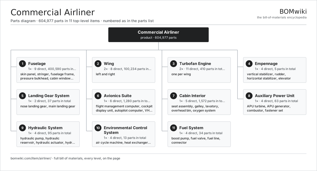
| # | Part | Qty | What it does |
|---|---|---|---|
| 1 | Fuselage 9 parts | 1× | Pressurised tube housing flight deck, cabin and cargo holds. |
| 2 | Wing 8 parts | 2× | left and right |
| 3 | Turbofan Engine 11 parts | 2× | one per wing |
| 4 | Empennage 4 parts | 1× | Tail surfaces providing pitch and yaw stability and control. |
| 5 | Landing Gear System 2 parts | 1× | Retractable tricycle gear with nose and two main legs. |
| 6 | Avionics Suite 6 parts | 1× | Flight deck computers, displays and radios. |
| 7 | Cabin Interior 5 parts | 1× | Passenger cabin furnishings and life-support. |
| 8 | Auxiliary Power Unit 4 parts | 1× | Tail-mounted gas turbine for ground/standby power. |
| 9 | Hydraulic System 4 parts | 1× | Three-channel 3000 psi hydraulic power. |
| 10 | Environmental Control System 4 parts | 1× | Cabin pressurisation, air-conditioning and bleed-air management. |
| 11 | Fuel System 4 parts | 1× | Fuel storage, transfer and distribution. |
Diagrams & photos


3D model
No 3D model yet. Have a CAD file of this? Add a 3D model. STL renders right on this page; STEP, FreeCAD, and OpenSCAD sources are welcome too (openly licensed, like all 3D models on BOMwiki).
Build & assembly graph
expand / collapse · shared sub-assemblies converge · links to related products · est. labourTap an assembly to expand/collapse · tap a part to open it · use “Open page” for any node · drag to pan, scroll to zoom.
Bill of materials for Commercial Airliner
11 top-level lines · 155 rows shown · 604,977 parts total · indented to 3 levels| # | Item / sub-assembly | Part no. | Qty/assy | Ext. qty | Parts | Type |
|---|---|---|---|---|---|---|
| 1 | Fuselage 9 parts | airliner-fuselage | 1× | 1 | 400,590 | assembly |
| 1.1 | Skin Panel | airliner-skin-panel | 24× | 24 | · | part |
| 1.2 | Stringer | airliner-stringer | 80× | 80 | · | part |
| 1.3 | Fuselage Frame | airliner-frame | 40× | 40 | · | part |
| 1.4 | Pressure Bulkhead | airliner-pressure-bulkhead | 2× | 2 | · | part |
| 1.5 | Cabin Window | airliner-cabin-window | 60× | 60 | · | part |
| 1.6 | Passenger Door 4 parts | airliner-passenger-door | 4× | 4 | 33 | assembly |
| 1.6.1 | Door Panel | airliner-door-panel | 1× | 4 | · | part |
| 1.6.2 | Evacuation Slide | airliner-evacuation-slide | 1× | 4 | · | part |
| 1.6.3 | Door Seal | airliner-door-seal | 1× | 4 | · | part |
| 1.6.4 | Fastener Set | fastener-set | 30× | 120 | · | part |
| 1.7 | Cargo Door 3 parts | airliner-cargo-door | 2× | 2 | 26 | assembly |
| 1.7.1 | Door Panel | airliner-door-panel | 1× | 2 | · | part |
| 1.7.2 | Door Seal | airliner-door-seal | 1× | 2 | · | part |
| 1.7.3 | Fastener Set | fastener-set | 24× | 48 | · | part |
| 1.8 | Solid Rivet | airliner-rivet | 400000× | 400,000 | · | part |
| 1.9 | Fastener Set | fastener-set | 200× | 200 | · | part |
| 2 | Wing 8 parts | airliner-wing | 2× | 2 | 100,234 | assembly |
| 2.1 | Wing Box 5 parts | airliner-wing-box | 1× | 2 | 210 | assembly |
| 2.1.1 | Wing Spar | airliner-spar | 2× | 4 | · | part |
| 2.1.2 | Wing Rib | airliner-wing-rib | 24× | 48 | · | part |
| 2.1.3 | Wing Skin | airliner-wing-skin | 4× | 8 | · | part |
| 2.1.4 | Stringer | airliner-stringer | 30× | 60 | · | part |
| 2.1.5 | Fastener Set | fastener-set | 150× | 300 | · | part |
| 2.2 | Leading-Edge Slat | airliner-slat | 5× | 10 | · | part |
| 2.3 | Trailing-Edge Flap | airliner-flap | 2× | 4 | · | part |
| 2.4 | Aileron | airliner-aileron | 1× | 2 | · | part |
| 2.5 | Spoiler | airliner-spoiler | 5× | 10 | · | part |
| 2.6 | Winglet | airliner-winglet | 1× | 2 | · | part |
| 2.7 | Integral Fuel Tank 2 parts | airliner-fuel-tank | 1× | 2 | 10 | assembly |
| 2.7.1 | Boost Pump | airliner-fuel-pump | 2× | 4 | · | part |
| 2.7.2 | O-Ring Set | oring-set | 8× | 16 | · | part |
| 2.8 | Solid Rivet | airliner-rivet | 100000× | 200,000 | · | part |
| 3 | Turbofan Engine 11 parts | airliner-engine | 2× | 2 | 410 | assembly |
| 3.1 | Fan Module | airliner-fan | 1× | 2 | · | part |
| 3.2 | Fan Case | airliner-fan-case | 1× | 2 | · | part |
| 3.3 | Low-Pressure Compressor 2 parts | airliner-lp-compressor | 1× | 2 | 6 | assembly |
| 3.3.1 | Compressor Stage | airliner-compressor-stage | 4× | 8 | · | part |
| 3.3.2 | Ball Bearing | ball-bearing | 2× | 4 | · | part |
| 3.4 | High-Pressure Compressor 2 parts | airliner-hp-compressor | 1× | 2 | 11 | assembly |
| 3.4.1 | Compressor Stage | airliner-compressor-stage | 9× | 18 | · | part |
| 3.4.2 | Ball Bearing | ball-bearing | 2× | 4 | · | part |
| 3.5 | Combustor 2 parts | airliner-combustor | 1× | 2 | 21 | assembly |
| 3.5.1 | Combustor Liner | airliner-combustor-liner | 1× | 2 | · | part |
| 3.5.2 | Fuel Nozzle | airliner-fuel-nozzle | 20× | 40 | · | part |
| 3.6 | High-Pressure Turbine 2 parts | airliner-hp-turbine | 1× | 2 | 2 | assembly |
| 3.6.1 | Turbine Stage | airliner-turbine-stage | 1× | 2 | · | part |
| 3.6.2 | Ball Bearing | ball-bearing | 1× | 2 | · | part |
| 3.7 | Low-Pressure Turbine 2 parts | airliner-lp-turbine | 1× | 2 | 6 | assembly |
| 3.7.1 | Turbine Stage | airliner-turbine-stage | 5× | 10 | · | part |
| 3.7.2 | Ball Bearing | ball-bearing | 1× | 2 | · | part |
| 3.8 | Accessory Gearbox 3 parts | airliner-accessory-gearbox | 1× | 2 | 24 | assembly |
| 3.8.1 | Spur Gear | airliner-gear | 12× | 24 | · | part |
| 3.8.2 | Ball Bearing | ball-bearing | 6× | 12 | · | part |
| 3.8.3 | Oil Seal | oil-seal | 6× | 12 | · | part |
| 3.9 | FADEC 4 parts | airliner-fadec | 1× | 2 | 312 | assembly |
| 3.9.1 | Bare PCB | pcb-bare | 2× | 4 | · | part |
| 3.9.2 | Microcontroller | mcu | 2× | 4 | · | part |
| 3.9.3 | SMD Passive (R/C/L) | smd-passives | 300× | 600 | · | part |
| 3.9.4 | Connector | connector | 8× | 16 | · | part |
| 3.10 | Nacelle | airliner-nacelle | 1× | 2 | · | part |
| 3.11 | Thrust Reverser 2 parts | airliner-thrust-reverser | 1× | 2 | 25 | assembly |
| 3.11.1 | Reverser Cascade | airliner-reverser-cascade | 1× | 2 | · | part |
| 3.11.2 | Hydraulic Actuator 3 parts + deeper › | airliner-actuator | 4× | 8 | 6 | assembly |
| 4 | Empennage 4 parts | airliner-empennage | 1× | 1 | 5 | assembly |
| 4.1 | Vertical Stabilizer | airliner-vertical-stabilizer | 1× | 1 | · | part |
| 4.2 | Rudder | airliner-rudder | 1× | 1 | · | part |
| 4.3 | Horizontal Stabilizer | airliner-horizontal-stabilizer | 1× | 1 | · | part |
| 4.4 | Elevator | airliner-elevator | 2× | 2 | · | part |
| 5 | Landing Gear System 2 parts | airliner-landing-gear | 1× | 1 | 37 | assembly |
| 5.1 | Nose Landing Gear 4 parts | airliner-nose-gear | 1× | 1 | 11 | assembly |
| 5.1.1 | Oleo Strut | airliner-oleo-strut | 1× | 1 | · | part |
| 5.1.2 | Wheel | airliner-wheel | 2× | 2 | · | part |
| 5.1.3 | Tire | airliner-tire | 2× | 2 | · | part |
| 5.1.4 | Hydraulic Actuator 3 parts + deeper › | airliner-actuator | 1× | 1 | 6 | assembly |
| 5.2 | Main Landing Gear 5 parts | airliner-main-gear | 2× | 2 | 13 | assembly |
| 5.2.1 | Oleo Strut | airliner-oleo-strut | 1× | 2 | · | part |
| 5.2.2 | Wheel | airliner-wheel | 2× | 4 | · | part |
| 5.2.3 | Tire | airliner-tire | 2× | 4 | · | part |
| 5.2.4 | Carbon Brake | airliner-carbon-brake | 2× | 4 | · | part |
| 5.2.5 | Hydraulic Actuator 3 parts + deeper › | airliner-actuator | 1× | 2 | 6 | assembly |
| 6 | Avionics Suite 6 parts | airliner-avionics | 1× | 1 | 1,280 | assembly |
| 6.1 | Flight Management Computer 4 parts | airliner-fmc | 1× | 1 | 517 | assembly |
| 6.1.1 | Bare PCB | pcb-bare | 3× | 3 | · | part |
| 6.1.2 | Microcontroller | mcu | 2× | 2 | · | part |
| 6.1.3 | SMD Passive (R/C/L) | smd-passives | 500× | 500 | · | part |
| 6.1.4 | Connector | connector | 12× | 12 | · | part |
| 6.2 | Cockpit Display Unit 4 parts | airliner-display-unit | 6× | 6 | 6 | assembly |
| 6.2.1 | LCD Panel | lcd-panel | 1× | 6 | · | part |
| 6.2.2 | Bare PCB | pcb-bare | 1× | 6 | · | part |
| 6.2.3 | Microcontroller | mcu | 1× | 6 | · | part |
| 6.2.4 | Connector | connector | 3× | 18 | · | part |
| 6.3 | Autopilot Computer 4 parts | airliner-autopilot | 1× | 1 | 310 | assembly |
| 6.3.1 | Bare PCB | pcb-bare | 2× | 2 | · | part |
| 6.3.2 | Microcontroller | mcu | 2× | 2 | · | part |
| 6.3.3 | SMD Passive (R/C/L) | smd-passives | 300× | 300 | · | part |
| 6.3.4 | Relay | relay | 6× | 6 | · | part |
| 6.4 | VHF Radio 4 parts | airliner-radio | 2× | 2 | 206 | assembly |
| 6.4.1 | Bare PCB | pcb-bare | 1× | 2 | · | part |
| 6.4.2 | Microcontroller | mcu | 1× | 2 | · | part |
| 6.4.3 | SMD Passive (R/C/L) | smd-passives | 200× | 400 | · | part |
| 6.4.4 | Connector | connector | 4× | 8 | · | part |
| 6.5 | Transponder | airliner-transponder | 1× | 1 | · | part |
| 6.6 | Weather Radar 3 parts | airliner-weather-radar | 1× | 1 | 4 | assembly |
| 6.6.1 | Radar Antenna | airliner-radar-antenna | 1× | 1 | · | part |
| 6.6.2 | Bare PCB | pcb-bare | 2× | 2 | · | part |
| 6.6.3 | Microcontroller | mcu | 1× | 1 | · | part |
| 7 | Cabin Interior 5 parts | airliner-cabin | 1× | 1 | 1,572 | assembly |
| 7.1 | Seat Assembly 5 parts | seat-assembly | 180× | 180 | 7 | assembly |
| 7.1.1 | Seat Frame | seat-frame | 1× | 180 | · | part |
| 7.1.2 | Seat Foam | seat-foam | 2× | 360 | · | part |
| 7.1.3 | Seat Cover | seat-cover | 1× | 180 | · | part |
| 7.1.4 | Seat Motor | seat-motor | 2× | 360 | · | part |
| 7.1.5 | Seat Heater Mat | seat-heater | 1× | 180 | · | part |
| 7.2 | Galley 3 parts | airliner-galley | 2× | 2 | 8 | assembly |
| 7.2.1 | Galley Cart | airliner-galley-cart | 4× | 8 | · | part |
| 7.2.2 | Galley Oven | airliner-galley-oven | 2× | 4 | · | part |
| 7.2.3 | Wire Bundle | wire-bundle | 2× | 4 | · | part |
| 7.3 | Lavatory 2 parts | airliner-lavatory | 3× | 3 | 2 | assembly |
| 7.3.1 | Vacuum Toilet | airliner-vacuum-toilet | 1× | 3 | · | part |
| 7.3.2 | Water Tank | airliner-water-tank | 1× | 3 | · | part |
| 7.4 | Overhead Bin | airliner-overhead-bin | 30× | 30 | · | part |
| 7.5 | Oxygen System 2 parts | airliner-oxygen-system | 1× | 1 | 260 | assembly |
| 7.5.1 | Chemical Oxygen Generator | airliner-oxygen-generator | 60× | 60 | · | part |
| 7.5.2 | Oxygen Mask | airliner-oxygen-mask | 200× | 200 | · | part |
| 8 | Auxiliary Power Unit 4 parts | airliner-apu | 1× | 1 | 63 | assembly |
| 8.1 | APU Turbine | airliner-apu-turbine | 1× | 1 | · | part |
| 8.2 | APU Generator | airliner-apu-generator | 1× | 1 | · | part |
| 8.3 | Combustor 2 parts | airliner-combustor | 1× | 1 | 21 | assembly |
| 8.3.1 | Combustor Liner | airliner-combustor-liner | 1× | 1 | · | part |
| 8.3.2 | Fuel Nozzle | airliner-fuel-nozzle | 20× | 20 | · | part |
| 8.4 | Fastener Set | fastener-set | 40× | 40 | · | part |
| 9 | Hydraulic System 4 parts | airliner-hydraulic-system | 1× | 1 | 95 | assembly |
| 9.1 | Hydraulic Pump 3 parts | airliner-hydraulic-pump | 3× | 3 | 8 | assembly |
| 9.1.1 | Ball Bearing | ball-bearing | 2× | 6 | · | part |
| 9.1.2 | Oil Seal | oil-seal | 2× | 6 | · | part |
| 9.1.3 | O-Ring Set | oring-set | 4× | 12 | · | part |
| 9.2 | Hydraulic Reservoir | airliner-reservoir | 3× | 3 | · | part |
| 9.3 | Hydraulic Actuator 3 parts | airliner-actuator | 8× | 8 | 6 | assembly |
| 9.3.1 | Actuator Cylinder | airliner-actuator-cylinder | 1× | 8 | · | part |
| 9.3.2 | O-Ring Set | oring-set | 3× | 24 | · | part |
| 9.3.3 | Oil Seal | oil-seal | 2× | 16 | · | part |
| 9.4 | Hydraulic Line | airliner-hydraulic-line | 20× | 20 | · | part |
| 10 | Environmental Control System 4 parts | airliner-ecs | 1× | 1 | 13 | assembly |
| 10.1 | Air Cycle Machine 2 parts | airliner-air-cycle-machine | 2× | 2 | 4 | assembly |
| 10.1.1 | Ball Bearing | ball-bearing | 2× | 4 | · | part |
| 10.1.2 | Oil Seal | oil-seal | 2× | 4 | · | part |
| 10.2 | Heat Exchanger | airliner-heat-exchanger | 2× | 2 | · | part |
| 10.3 | Outflow Valve | airliner-outflow-valve | 1× | 1 | · | part |
| 10.4 | Bleed Air Valve | airliner-bleed-valve | 2× | 2 | · | part |
| 11 | Fuel System 4 parts | airliner-fuel-system | 1× | 1 | 34 | assembly |
| 11.1 | Boost Pump | airliner-fuel-pump | 4× | 4 | · | part |
| 11.2 | Fuel Valve | airliner-fuel-valve | 6× | 6 | · | part |
| 11.3 | Fuel Line | airliner-fuel-line | 16× | 16 | · | part |
| 11.4 | Connector | connector | 8× | 8 | · | part |
Something wrong in this list? Report a problem with this BOM.
Related products
same domain, ranked by shared parts Helicopter
16,033 parts · shares 10 with this page
 Amphibious Seaplane
163 parts · shares 9 with this page
 Non-Rigid Airship (Blimp)
336 parts · shares 9 with this page
 Business Jet
1,654 parts · shares 8 with this page
 Full-Flight Simulator
379 parts · shares 8 with this page
 Jumbo Jet (747-class)
5,643,733 parts · shares 8 with this page
Sourcing: possible vendors
Browse the supplier directory → Prices, MOQ, and lead times are algorithmic estimates, not quotes, and not claims about these companies. Company mappings are curated by keyword; est. price band $50k–$300M. How estimates work| Vendor | HQ | Specialty | MOQ | Lead time |
|---|---|---|---|---|
|
🇺🇸Boeing
boeing.com ↗
|
Arlington, US | Aerospace OEM | made to order | 40–80 wks |
|
🇫🇷Airbus
airbus.com ↗
|
Toulouse, FR | Aerospace OEM | made to order | 40–80 wks |
| lockheedmartin.com ↗ | Bethesda, US | Aerospace & defense | made to order | 40–80 wks |
|
🇧🇷Embraer
embraer.com ↗
|
São José dos Campos, BR | Aircraft OEM | made to order | 40–80 wks |
| txtav.com ↗ | Wichita, US | Aircraft OEM | made to order | 40–80 wks |
1,130-word article