Turboprop Airliner
ProductOverview
The Turboprop Airliner is a pressurised twin-engine regional aircraft built to carry around 70 passengers over routes of up to 1,500 km. It fills the gap between small commuter aircraft and regional jets, serving thin routes where a jet would burn too much fuel and where the trip is short enough that the lower cruise speed costs only a few minutes. The propeller turbine combination is the reason it exists: at the 300 to 500 km stage lengths it is built for, a turboprop uses materially less fuel than a jet of the same size, because the large slow-turning propeller moves a big mass of air at modest speed, which is an efficient way to make thrust below about 600 km/h.
The aircraft is built around a circular-section pressurised Fuselage, a high-mounted Wing, and a T-tail Empennage. Two Turboprop Engine units hang from the wing in Nacelle pods, each driving a Propeller. The high wing keeps the propellers well clear of the ground, lets the fuselage sit low for easy boarding, and leaves a clean underside for the Landing Gear to retract into the nacelles and nose.
Airframe
The Airframe is a conventional aluminium semi-monocoque. The fuselage is a stack of 64 Fuselage Frame rings tied together by 120 Stringer runs, with Skin Panel sheet riveted over the top to form the pressure shell. A domed Pressure Bulkhead closes each end of the pressurised volume, so the cabin behaves as a sealed cylinder that can hold a pressure difference of about 6.5 psi between inside and outside at altitude. Rows of Cabin Window units and two plug-type Cabin Door assemblies, each with a built-in Airstair, break the shell, and every cut-out is reinforced so the skin around it does not crack under repeated pressure cycles.
The wing is a two-spar box. The Wing Spar members carry the bending load, the Wing Rib sections hold the aerofoil shape, and the Wing Skin panels close the box and double as the walls of the integral fuel tank. Roll comes from an outboard Aileron, lift at low speed from a double-slotted Flap, and lift dumping on landing from a Spoiler on the upper surface. The T-tail puts the Horizontal Stabiliser up out of the propeller wash and wing downwash, which keeps pitch control clean.
Powerplant and Propeller
Each Turboprop Engine is a free-turbine turboprop. Air enters through an Air Intake with an inertial separator that throws out rain and debris, is squeezed by the Compressor axial stages and a final Centrifugal Impeller, then burns with fuel in the annular Combustor. The hot gas first drives the Gas Generator Turbine, which turns only the compressor, and then a separate Power Turbine that is not mechanically tied to the compressor at all. Because the power turbine spins on its own Power Shaft, the propeller can be feathered and the gas generator left running, and engine start loads stay low. The free turbine drives the Reduction Gearbox, which steps the turbine's roughly 30,000 rpm down to the 1,000 rpm or so the propeller needs through two Helical Gear Pair stages. A FADEC controller meters fuel and protects the engine, and an Engine Oil System keeps the bearings and gears fed.
The Propeller is a six-blade constant-speed unit. The Propeller Governor senses propeller speed with a Governor Flyweight pair and adjusts blade pitch through the Pitch-Change Mechanism to hold the speed the crew set, so the propeller absorbs whatever power the engine makes at a fixed rpm. The same mechanism feathers the blades edge-on to the airflow if the engine fails, cutting drag, and reverses pitch on landing for braking. A Feathering Spring drives the blades to feather if oil pressure is lost, and a Propeller De-Ice heater stops ice forming on the blades.
Landing Gear and Flight Controls
The Landing Gear is a retractable tricycle layout. Each Main Gear Leg and the steerable Nose Gear Leg use an Oleo Strut, an oil-and-gas shock leg that absorbs the landing impact and damps the rebound. A Gear Retract Actuator raises and lowers each leg, and the Brake System uses Carbon Brake stacks with an Anti-Skid Valve on each wheel to stop without skidding on a wet runway.
The Flight Controls keep mechanical links to the primary surfaces: the Control Column and Rudder Pedal Set sets move the ailerons, elevators, and rudder through a Control Cable Run run of stainless cables and pulleys. This direct path is simple and keeps working even with the hydraulics off. The flaps are powered, driven from a central Flap Power Drive Unit so both wings always move together, and a Trim Actuator trims each axis. A Yaw Damper nudges the rudder to suppress the Dutch-roll wobble that a swept or high-aspect-ratio wing tends to show.
Systems
The Fuel System holds fuel in an integral Fuel Tank inside each wing box, with Boost Pump pumps feeding the engines and a Crossfeed Valve letting either tank feed either engine to keep the aircraft balanced. The Avionics are an integrated glass cockpit: four Flight Display screens show flight, engine, and system data, a Flight Management System plans and flies the route, the Autopilot holds it, and a nose Weather Radar paints storms ahead. Air for the cabin comes from the Environmental Control system, where engine Bleed Air System is cooled by an Air Cycle Machine and metered by a Pressure Controller against an Outflow Valve to hold a comfortable cabin altitude. Ice is shed from the wing and tail by a pneumatic De-Ice System.
Inside, the Cabin Interior seats passengers in Passenger Seat rows under Overhead Bin stowage, with a forward Galley and an aft Lavatory. The Electrical System system generates power from two engine Starter-Generator units that also start the engines, backed by an Auxiliary Power Unit for ground power and a Battery for emergencies.
Variants and Use
The same airframe stretches and shrinks. A shorter version seats around 50, the baseline seats 70, and a stretched fuselage takes the count past 80 by adding frame bays fore and aft of the wing. Operators specify a cargo or quick-change interior for freight and combi work, and some buyers take a higher-power engine rating for hot-and-high airports where thinner air costs takeoff thrust. The aircraft earns its living on short regional links, island services, and feeder routes into hub airports, the places where a 30 to 60 minute leg makes the turboprop's fuel saving worth more than the extra speed of a jet.
Turboprop Airliner parts and their functions
10 top-level parts · 3,298 parts in total · full bill of materials below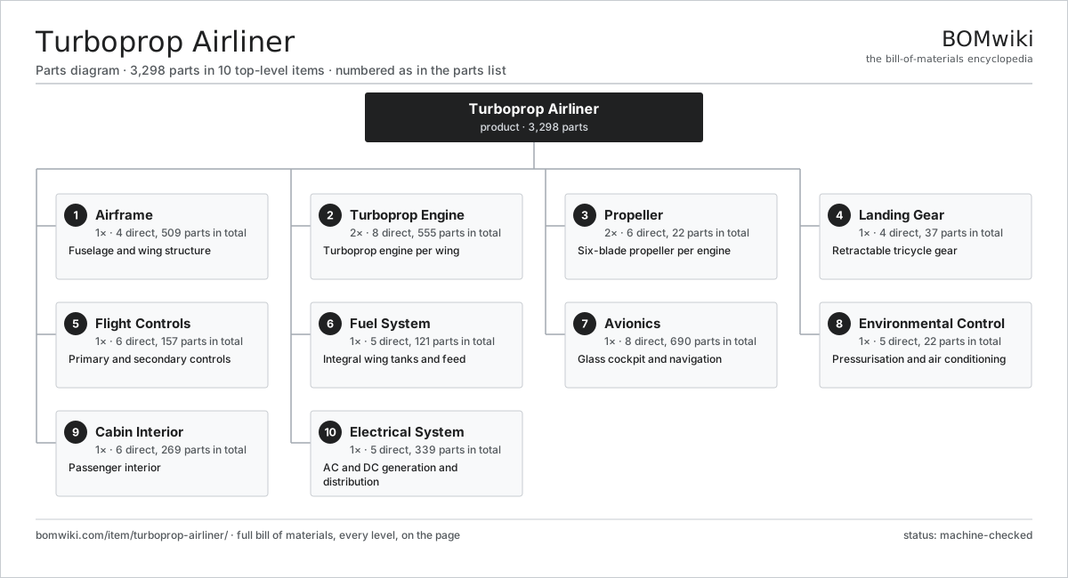
| # | Part | Qty | What it does |
|---|---|---|---|
| 1 | Airframe 4 parts | 1× | Fuselage and wing structure |
| 2 | Turboprop Engine 8 parts | 2× | Turboprop engine per wing |
| 3 | Propeller 6 parts | 2× | Six-blade propeller per engine |
| 4 | Landing Gear 4 parts | 1× | Retractable tricycle gear |
| 5 | Flight Controls 6 parts | 1× | Primary and secondary controls |
| 6 | Fuel System 5 parts | 1× | Integral wing tanks and feed |
| 7 | Avionics 8 parts | 1× | Glass cockpit and navigation |
| 8 | Environmental Control 5 parts | 1× | Pressurisation and air conditioning |
| 9 | Cabin Interior 6 parts | 1× | Passenger interior |
| 10 | Electrical System 5 parts | 1× | AC and DC generation and distribution |
3D model
No 3D model yet. Have a CAD file of this? Add a 3D model. STL renders right on this page; STEP, FreeCAD, and OpenSCAD sources are welcome too (openly licensed, like all 3D models on BOMwiki).
Build & assembly graph
expand / collapse · shared sub-assemblies converge · links to related products · est. labourTap an assembly to expand/collapse · tap a part to open it · use “Open page” for any node · drag to pan, scroll to zoom.
Bill of materials for Turboprop Airliner
10 top-level lines · 215 rows shown · 3,298 parts total · indented to 3 levels| # | Item / sub-assembly | Part no. | Qty/assy | Ext. qty | Parts | Type |
|---|---|---|---|---|---|---|
| 1 | Airframe 4 parts | turboprop-airliner-airframe | 1× | 1 | 509 | assembly |
| 1.1 | Fuselage 8 parts | turboprop-airliner-fuselage | 1× | 1 | 296 | assembly |
| 1.1.1 | Fuselage Frame | turboprop-airliner-fuselage-frame | 64× | 64 | · | part |
| 1.1.2 | Stringer | turboprop-airliner-stringer | 120× | 120 | · | part |
| 1.1.3 | Skin Panel | turboprop-airliner-skin-panel | 40× | 40 | · | part |
| 1.1.4 | Pressure Bulkhead | turboprop-airliner-bulkhead | 2× | 2 | · | part |
| 1.1.5 | Cabin Window | turboprop-airliner-cabin-window | 60× | 60 | · | part |
| 1.1.6 | Cabin Door 4 parts + deeper › | turboprop-airliner-cabin-door | 2× | 2 | 4 | assembly |
| 1.1.7 | Cargo Door | turboprop-airliner-cargo-door | 1× | 1 | · | part |
| 1.1.8 | Fastener Set | fastener-set | 1× | 1 | · | part |
| 1.2 | Wing 7 parts | turboprop-airliner-wing | 2× | 2 | 96 | assembly |
| 1.2.1 | Wing Spar | turboprop-airliner-wing-spar | 2× | 4 | · | part |
| 1.2.2 | Wing Rib | turboprop-airliner-wing-rib | 24× | 48 | · | part |
| 1.2.3 | Wing Skin | turboprop-airliner-wing-skin | 8× | 16 | · | part |
| 1.2.4 | Aileron | turboprop-airliner-aileron | 1× | 2 | · | part |
| 1.2.5 | Flap 3 parts + deeper › | turboprop-airliner-flap | 2× | 4 | 29 | assembly |
| 1.2.6 | Spoiler | turboprop-airliner-spoiler | 2× | 4 | · | part |
| 1.2.7 | Winglet | turboprop-airliner-winglet | 1× | 2 | · | part |
| 1.3 | Empennage 4 parts | turboprop-airliner-empennage | 1× | 1 | 5 | assembly |
| 1.3.1 | Vertical Stabiliser | turboprop-airliner-vertical-stabiliser | 1× | 1 | · | part |
| 1.3.2 | Horizontal Stabiliser | turboprop-airliner-horizontal-stabiliser | 1× | 1 | · | part |
| 1.3.3 | Rudder | turboprop-airliner-rudder | 1× | 1 | · | part |
| 1.3.4 | Elevator | turboprop-airliner-elevator | 2× | 2 | · | part |
| 1.4 | Nacelle 4 parts | turboprop-airliner-nacelle | 2× | 2 | 8 | assembly |
| 1.4.1 | Cowling | turboprop-airliner-cowling | 1× | 2 | · | part |
| 1.4.2 | Engine Mount 2 parts + deeper › | turboprop-airliner-engine-mount | 1× | 2 | 5 | assembly |
| 1.4.3 | Firewall | turboprop-airliner-firewall | 1× | 2 | · | part |
| 1.4.4 | Air Intake | turboprop-airliner-air-intake | 1× | 2 | · | part |
| 2 | Turboprop Engine 8 parts | turboprop-airliner-powerplant | 2× | 2 | 555 | assembly |
| 2.1 | Compressor 4 parts | turboprop-airliner-compressor | 1× | 2 | 126 | assembly |
| 2.1.1 | Compressor Disc | turboprop-airliner-compressor-disc | 3× | 6 | · | part |
| 2.1.2 | Compressor Blade | turboprop-airliner-compressor-blade | 120× | 240 | · | part |
| 2.1.3 | Centrifugal Impeller | turboprop-airliner-impeller | 1× | 2 | · | part |
| 2.1.4 | Ball Bearing | ball-bearing | 2× | 4 | · | part |
| 2.2 | Combustor 3 parts | turboprop-airliner-combustor | 1× | 2 | 17 | assembly |
| 2.2.1 | Combustor Liner | turboprop-airliner-combustor-liner | 1× | 2 | · | part |
| 2.2.2 | Fuel Nozzle | turboprop-airliner-fuel-nozzle | 14× | 28 | · | part |
| 2.2.3 | Igniter | turboprop-airliner-igniter | 2× | 4 | · | part |
| 2.3 | Gas Generator Turbine 4 parts | turboprop-airliner-gas-turbine | 1× | 2 | 93 | assembly |
| 2.3.1 | Turbine Disc | turboprop-airliner-turbine-disc | 1× | 2 | · | part |
| 2.3.2 | Turbine Blade | turboprop-airliner-turbine-blade | 60× | 120 | · | part |
| 2.3.3 | Nozzle Guide Vane | turboprop-airliner-nozzle-guide-vane | 30× | 60 | · | part |
| 2.3.4 | Ball Bearing | ball-bearing | 2× | 4 | · | part |
| 2.4 | Power Turbine 4 parts | turboprop-airliner-power-turbine | 1× | 2 | 85 | assembly |
| 2.4.1 | Turbine Disc | turboprop-airliner-turbine-disc | 2× | 4 | · | part |
| 2.4.2 | Turbine Blade | turboprop-airliner-turbine-blade | 80× | 160 | · | part |
| 2.4.3 | Power Shaft | turboprop-airliner-power-shaft | 1× | 2 | · | part |
| 2.4.4 | Ball Bearing | ball-bearing | 2× | 4 | · | part |
| 2.5 | Reduction Gearbox 4 parts | turboprop-airliner-reduction-gearbox | 1× | 2 | 12 | assembly |
| 2.5.1 | Helical Gear Pair | gear-pair | 2× | 4 | · | part |
| 2.5.2 | Gearbox Housing | gearbox-housing | 1× | 2 | · | part |
| 2.5.3 | Ball Bearing | ball-bearing | 6× | 12 | · | part |
| 2.5.4 | Oil Seal | oil-seal | 3× | 6 | · | part |
| 2.6 | Accessory Gearbox 3 parts | turboprop-airliner-engine-accessory | 1× | 2 | 8 | assembly |
| 2.6.1 | Helical Gear Pair | gear-pair | 3× | 6 | · | part |
| 2.6.2 | Gearbox Housing | gearbox-housing | 1× | 2 | · | part |
| 2.6.3 | Ball Bearing | ball-bearing | 4× | 8 | · | part |
| 2.7 | FADEC 4 parts | turboprop-airliner-fadec | 1× | 2 | 210 | assembly |
| 2.7.1 | Bare PCB | pcb-bare | 2× | 4 | · | part |
| 2.7.2 | Microcontroller | mcu | 2× | 4 | · | part |
| 2.7.3 | SMD Passive (R/C/L) | smd-passives | 200× | 400 | · | part |
| 2.7.4 | Connector | connector | 6× | 12 | · | part |
| 2.8 | Engine Oil System 3 parts | turboprop-airliner-engine-oil-system | 1× | 2 | 4 | assembly |
| 2.8.1 | Oil Pump 2 parts + deeper › | turboprop-airliner-oil-pump | 1× | 2 | 2 | assembly |
| 2.8.2 | Oil Cooler | turboprop-airliner-oil-cooler | 1× | 2 | · | part |
| 2.8.3 | Oil Filter | turboprop-airliner-oil-filter | 1× | 2 | · | part |
| 3 | Propeller 6 parts | turboprop-airliner-propeller | 2× | 2 | 22 | assembly |
| 3.1 | Propeller Blade | turboprop-airliner-prop-blade | 6× | 12 | · | part |
| 3.2 | Propeller Hub | turboprop-airliner-prop-hub | 1× | 2 | · | part |
| 3.3 | Pitch-Change Mechanism 3 parts | turboprop-airliner-pitch-mechanism | 1× | 2 | 3 | assembly |
| 3.3.1 | Pitch Piston | turboprop-airliner-pitch-piston | 1× | 2 | · | part |
| 3.3.2 | Feathering Spring | turboprop-airliner-feather-spring | 1× | 2 | · | part |
| 3.3.3 | O-Ring Set | oring-set | 1× | 2 | · | part |
| 3.4 | Propeller Governor 3 parts | turboprop-airliner-prop-governor | 1× | 2 | 4 | assembly |
| 3.4.1 | Helical Gear Pair | gear-pair | 1× | 2 | · | part |
| 3.4.2 | Governor Flyweight | turboprop-airliner-flyweight | 2× | 4 | · | part |
| 3.4.3 | Coil Spring | coil-spring | 1× | 2 | · | part |
| 3.5 | Spinner | turboprop-airliner-spinner | 1× | 2 | · | part |
| 3.6 | Propeller De-Ice 2 parts | turboprop-airliner-prop-deice | 1× | 2 | 7 | assembly |
| 3.6.1 | Heating Element | heating-element | 6× | 12 | · | part |
| 3.6.2 | Slip Ring | turboprop-airliner-slip-ring | 1× | 2 | · | part |
| 4 | Landing Gear 4 parts | turboprop-airliner-landing-gear | 1× | 1 | 37 | assembly |
| 4.1 | Main Gear Leg 4 parts | turboprop-airliner-main-gear | 2× | 2 | 6 | assembly |
| 4.1.1 | Oleo Strut | turboprop-airliner-oleo-strut | 1× | 2 | · | part |
| 4.1.2 | Wheel | turboprop-airliner-wheel | 2× | 4 | · | part |
| 4.1.3 | Tire | turboprop-airliner-tire | 2× | 4 | · | part |
| 4.1.4 | Torque Link | turboprop-airliner-torque-link | 1× | 2 | · | part |
| 4.2 | Nose Gear Leg 4 parts | turboprop-airliner-nose-gear | 1× | 1 | 7 | assembly |
| 4.2.1 | Oleo Strut | turboprop-airliner-oleo-strut | 1× | 1 | · | part |
| 4.2.2 | Wheel | turboprop-airliner-wheel | 2× | 2 | · | part |
| 4.2.3 | Tire | turboprop-airliner-tire | 2× | 2 | · | part |
| 4.2.4 | Steering Actuator 2 parts + deeper › | turboprop-airliner-steering-actuator | 1× | 1 | 2 | assembly |
| 4.3 | Gear Retract Actuator 2 parts | turboprop-airliner-gear-actuator | 3× | 3 | 2 | assembly |
| 4.3.1 | Hydraulic Cylinder | turboprop-airliner-hydraulic-cylinder | 1× | 3 | · | part |
| 4.3.2 | O-Ring Set | oring-set | 1× | 3 | · | part |
| 4.4 | Brake System 3 parts | turboprop-airliner-brake-system | 1× | 1 | 12 | assembly |
| 4.4.1 | Carbon Brake | turboprop-airliner-carbon-brake | 4× | 4 | · | part |
| 4.4.2 | Anti-Skid Valve | turboprop-airliner-antiskid-valve | 4× | 4 | · | part |
| 4.4.3 | Pressure Sensor | pressure-sensor | 4× | 4 | · | part |
| 5 | Flight Controls 6 parts | turboprop-airliner-flight-controls | 1× | 1 | 157 | assembly |
| 5.1 | Control Column | turboprop-airliner-control-column | 2× | 2 | · | part |
| 5.2 | Rudder Pedal Set | turboprop-airliner-rudder-pedal | 2× | 2 | · | part |
| 5.3 | Control Cable Run | turboprop-airliner-control-cable | 1× | 1 | · | part |
| 5.4 | Flap Power Drive Unit 3 parts | turboprop-airliner-flap-pdu | 1× | 1 | 51 | assembly |
| 5.4.1 | Servo Motor 4 parts + deeper › | servo-motor | 2× | 2 | 24 | assembly |
| 5.4.2 | Helical Gear Pair | gear-pair | 2× | 2 | · | part |
| 5.4.3 | Gearbox Housing | gearbox-housing | 1× | 1 | · | part |
| 5.5 | Trim Actuator 2 parts | turboprop-airliner-trim-actuator | 3× | 3 | 25 | assembly |
| 5.5.1 | Servo Motor 4 parts + deeper › | servo-motor | 1× | 3 | 24 | assembly |
| 5.5.2 | Ball Screw | ball-screw | 1× | 3 | · | part |
| 5.6 | Yaw Damper 3 parts | turboprop-airliner-yaw-damper | 1× | 1 | 26 | assembly |
| 5.6.1 | Servo Motor 4 parts + deeper › | servo-motor | 1× | 1 | 24 | assembly |
| 5.6.2 | Bare PCB | pcb-bare | 1× | 1 | · | part |
| 5.6.3 | Microcontroller | mcu | 1× | 1 | · | part |
| 6 | Fuel System 5 parts | turboprop-airliner-fuel-system | 1× | 1 | 121 | assembly |
| 6.1 | Fuel Tank | turboprop-airliner-fuel-tank | 2× | 2 | · | part |
| 6.2 | Boost Pump 2 parts | turboprop-airliner-fuel-pump-boost | 4× | 4 | 25 | assembly |
| 6.2.1 | Servo Motor 4 parts + deeper › | servo-motor | 1× | 4 | 24 | assembly |
| 6.2.2 | Oil Seal | oil-seal | 1× | 4 | · | part |
| 6.3 | Fuel Control Unit 3 parts | turboprop-airliner-fuel-control | 2× | 2 | 4 | assembly |
| 6.3.1 | Helical Gear Pair | gear-pair | 1× | 2 | · | part |
| 6.3.2 | Pressure Sensor | pressure-sensor | 2× | 4 | · | part |
| 6.3.3 | O-Ring Set | oring-set | 1× | 2 | · | part |
| 6.4 | Crossfeed Valve | turboprop-airliner-crossfeed-valve | 1× | 1 | · | part |
| 6.5 | Fuel Quantity System 3 parts | turboprop-airliner-fuel-gauge | 1× | 1 | 10 | assembly |
| 6.5.1 | Fuel Probe | turboprop-airliner-fuel-probe | 8× | 8 | · | part |
| 6.5.2 | Bare PCB | pcb-bare | 1× | 1 | · | part |
| 6.5.3 | Microcontroller | mcu | 1× | 1 | · | part |
| 7 | Avionics 8 parts | turboprop-airliner-avionics | 1× | 1 | 690 | assembly |
| 7.1 | Flight Display 4 parts | turboprop-airliner-flight-display | 4× | 4 | 7 | assembly |
| 7.1.1 | LCD Panel | lcd-panel | 1× | 4 | · | part |
| 7.1.2 | Bare PCB | pcb-bare | 1× | 4 | · | part |
| 7.1.3 | Microcontroller | mcu | 1× | 4 | · | part |
| 7.1.4 | Connector | connector | 4× | 16 | · | part |
| 7.2 | Flight Management System 4 parts | turboprop-airliner-fms | 1× | 1 | 312 | assembly |
| 7.2.1 | Bare PCB | pcb-bare | 2× | 2 | · | part |
| 7.2.2 | Microcontroller | mcu | 2× | 2 | · | part |
| 7.2.3 | SMD Passive (R/C/L) | smd-passives | 300× | 300 | · | part |
| 7.2.4 | Connector | connector | 8× | 8 | · | part |
| 7.3 | Autopilot 3 parts | turboprop-airliner-autopilot | 1× | 1 | 76 | assembly |
| 7.3.1 | Bare PCB | pcb-bare | 2× | 2 | · | part |
| 7.3.2 | Microcontroller | mcu | 2× | 2 | · | part |
| 7.3.3 | Servo Motor 4 parts + deeper › | servo-motor | 3× | 3 | 24 | assembly |
| 7.4 | Air Data Computer 3 parts | turboprop-airliner-air-data | 2× | 2 | 5 | assembly |
| 7.4.1 | Bare PCB | pcb-bare | 1× | 2 | · | part |
| 7.4.2 | Microcontroller | mcu | 1× | 2 | · | part |
| 7.4.3 | Pressure Sensor | pressure-sensor | 3× | 6 | · | part |
| 7.5 | Attitude Reference 3 parts | turboprop-airliner-ahrs | 2× | 2 | 122 | assembly |
| 7.5.1 | Bare PCB | pcb-bare | 1× | 2 | · | part |
| 7.5.2 | Microcontroller | mcu | 1× | 2 | · | part |
| 7.5.3 | SMD Passive (R/C/L) | smd-passives | 120× | 240 | · | part |
| 7.6 | Weather Radar 3 parts | turboprop-airliner-weather-radar | 1× | 1 | 4 | assembly |
| 7.6.1 | Radar Antenna | turboprop-airliner-radar-antenna | 1× | 1 | · | part |
| 7.6.2 | Bare PCB | pcb-bare | 2× | 2 | · | part |
| 7.6.3 | Microcontroller | mcu | 1× | 1 | · | part |
| 7.7 | Transponder 3 parts | turboprop-airliner-transponder | 2× | 2 | 4 | assembly |
| 7.7.1 | Bare PCB | pcb-bare | 1× | 2 | · | part |
| 7.7.2 | Microcontroller | mcu | 1× | 2 | · | part |
| 7.7.3 | Connector | connector | 2× | 4 | · | part |
| 7.8 | VHF Radio 3 parts | turboprop-airliner-vhf-comm | 2× | 2 | 4 | assembly |
| 7.8.1 | Bare PCB | pcb-bare | 1× | 2 | · | part |
| 7.8.2 | Microcontroller | mcu | 1× | 2 | · | part |
| 7.8.3 | Connector | connector | 2× | 4 | · | part |
| 8 | Environmental Control 5 parts | turboprop-airliner-environmental | 1× | 1 | 22 | assembly |
| 8.1 | Bleed Air System 3 parts | turboprop-airliner-bleed-air | 1× | 1 | 5 | assembly |
| 8.1.1 | Bleed Valve | turboprop-airliner-bleed-valve | 2× | 2 | · | part |
| 8.1.2 | Pressure Sensor | pressure-sensor | 2× | 2 | · | part |
| 8.1.3 | Precooler | turboprop-airliner-precooler | 1× | 1 | · | part |
| 8.2 | Air Cycle Machine 3 parts | turboprop-airliner-air-cycle-machine | 1× | 1 | 4 | assembly |
| 8.2.1 | ACM Turbine | turboprop-airliner-acm-turbine | 1× | 1 | · | part |
| 8.2.2 | ACM Compressor | turboprop-airliner-acm-compressor | 1× | 1 | · | part |
| 8.2.3 | Ball Bearing | ball-bearing | 2× | 2 | · | part |
| 8.3 | Pressure Controller 3 parts | turboprop-airliner-pressure-controller | 1× | 1 | 4 | assembly |
| 8.3.1 | Bare PCB | pcb-bare | 1× | 1 | · | part |
| 8.3.2 | Microcontroller | mcu | 1× | 1 | · | part |
| 8.3.3 | Pressure Sensor | pressure-sensor | 2× | 2 | · | part |
| 8.4 | Outflow Valve | turboprop-airliner-outflow-valve | 1× | 1 | · | part |
| 8.5 | De-Ice System 2 parts | turboprop-airliner-deice-system | 1× | 1 | 8 | assembly |
| 8.5.1 | De-Ice Boot | turboprop-airliner-deice-boot | 6× | 6 | · | part |
| 8.5.2 | De-Ice Valve | turboprop-airliner-deice-valve | 2× | 2 | · | part |
| 9 | Cabin Interior 6 parts | turboprop-airliner-cabin | 1× | 1 | 269 | assembly |
| 9.1 | Passenger Seat 3 parts | turboprop-airliner-passenger-seat | 70× | 70 | 3 | assembly |
| 9.1.1 | Seat Frame | turboprop-airliner-seat-frame | 1× | 70 | · | part |
| 9.1.2 | Seat Cushion | turboprop-airliner-seat-cushion | 1× | 70 | · | part |
| 9.1.3 | Seatbelt | turboprop-airliner-seatbelt | 1× | 70 | · | part |
| 9.2 | Overhead Bin | turboprop-airliner-overhead-bin | 18× | 18 | · | part |
| 9.3 | Sidewall Panel | turboprop-airliner-sidewall-panel | 30× | 30 | · | part |
| 9.4 | Galley 3 parts | turboprop-airliner-galley | 1× | 1 | 3 | assembly |
| 9.4.1 | Heating Element | heating-element | 1× | 1 | · | part |
| 9.4.2 | Galley Chiller | turboprop-airliner-galley-chiller | 1× | 1 | · | part |
| 9.4.3 | Water Heater | turboprop-airliner-water-heater | 1× | 1 | · | part |
| 9.5 | Lavatory 2 parts | turboprop-airliner-lavatory | 1× | 1 | 2 | assembly |
| 9.5.1 | Vacuum Toilet | turboprop-airliner-vacuum-toilet | 1× | 1 | · | part |
| 9.5.2 | Water Heater | turboprop-airliner-water-heater | 1× | 1 | · | part |
| 9.6 | Cabin Lighting 3 parts | turboprop-airliner-cabin-lighting | 1× | 1 | 6 | assembly |
| 9.6.1 | Bare PCB | pcb-bare | 4× | 4 | · | part |
| 9.6.2 | Power Supply | power-supply | 1× | 1 | · | part |
| 9.6.3 | Wire Bundle | wire-bundle | 1× | 1 | · | part |
| 10 | Electrical System 5 parts | turboprop-airliner-electrical | 1× | 1 | 339 | assembly |
| 10.1 | Starter-Generator 3 parts | turboprop-airliner-generator | 2× | 2 | 24 | assembly |
| 10.1.1 | Stator Assembly 3 parts + deeper › | stator-assembly | 1× | 2 | 3 | assembly |
| 10.1.2 | Rotor Assembly 4 parts + deeper › | rotor-assembly | 1× | 2 | 19 | assembly |
| 10.1.3 | Ball Bearing | ball-bearing | 2× | 4 | · | part |
| 10.2 | Auxiliary Power Unit 3 parts | turboprop-airliner-apu | 1× | 1 | 214 | assembly |
| 10.2.1 | APU Turbine | turboprop-airliner-apu-turbine | 1× | 1 | · | part |
| 10.2.2 | Stator Assembly 3 parts + deeper › | stator-assembly | 1× | 1 | 3 | assembly |
| 10.2.3 | FADEC 4 parts + deeper › | turboprop-airliner-fadec | 1× | 1 | 210 | assembly |
| 10.3 | Battery | turboprop-airliner-battery | 2× | 2 | · | part |
| 10.4 | Transformer Rectifier 2 parts | turboprop-airliner-tru | 2× | 2 | 2 | assembly |
| 10.4.1 | Bare PCB | pcb-bare | 1× | 2 | · | part |
| 10.4.2 | Power Supply | power-supply | 1× | 2 | · | part |
| 10.5 | Power Distribution 3 parts | turboprop-airliner-distribution | 1× | 1 | 71 | assembly |
| 10.5.1 | Relay | relay | 30× | 30 | · | part |
| 10.5.2 | Connector | connector | 40× | 40 | · | part |
| 10.5.3 | Wire Bundle | wire-bundle | 1× | 1 | · | part |
Related products
same domain, ranked by shared parts Floatplane
813 parts · shares 20 with this page
Floatplane
813 parts · shares 20 with this page
 Flying Boat
4,224 parts · shares 20 with this page
Flying Boat
4,224 parts · shares 20 with this page
 Freighter Aircraft
6,717 parts · shares 20 with this page
Freighter Aircraft
6,717 parts · shares 20 with this page
 Tiltrotor Aircraft
2,528 parts · shares 17 with this page
Tiltrotor Aircraft
2,528 parts · shares 17 with this page
 Full-Flight Simulator
379 parts · shares 15 with this page
Full-Flight Simulator
379 parts · shares 15 with this page
 Gyroplane
168 parts · shares 16 with this page
Gyroplane
168 parts · shares 16 with this page
Sourcing: possible vendors
Browse the supplier directory → Prices, MOQ, and lead times are algorithmic estimates, not quotes, and not claims about these companies. Company mappings are curated by keyword; est. price band $50k–$300M. How estimates work| Vendor | HQ | Specialty | MOQ | Lead time |
|---|---|---|---|---|
|
🇺🇸Boeing
boeing.com ↗
|
Arlington, US | Aerospace OEM | made to order | 40–80 wks |
|
🇫🇷Airbus
airbus.com ↗
|
Toulouse, FR | Aerospace OEM | made to order | 40–80 wks |
| lockheedmartin.com ↗ | Bethesda, US | Aerospace & defense | made to order | 40–80 wks |
|
🇧🇷Embraer
embraer.com ↗
|
São José dos Campos, BR | Aircraft OEM | made to order | 40–80 wks |
| txtav.com ↗ | Wichita, US | Aircraft OEM | made to order | 40–80 wks |
1,245-word article