Geostationary Comsat
ProductOverview
A geostationary communications satellite is a relay station that never appears to move. Placed in a circular orbit about 35,786 km above the equator, it circles the Earth in exactly one day, so from the ground it hangs over a fixed longitude. That stillness is the whole point: a home dish or a ground station can be aimed once and left alone, because the satellite stays put in the sky for its entire 15-year life. The job it does is simple to state, receive a weak signal from one place and rebroadcast a strong one to a whole region, but doing it reliably for a decade and a half without service drives the entire design.
The satellite splits into a Bus Structure that provides housekeeping and a Communications Payload that carries the communications hardware. Supporting the payload are a Propulsion Subsystem subsystem that delivers and holds the orbit slot, a Power Subsystem subsystem, a Attitude Control that keeps the antennas pointed, a Thermal Control subsystem that sheds the heat of the amplifiers, and a Telemetry & Command subsystem that lets the ground control it.
Bus structure
The Bus Structure is the box-shaped platform the rest of the satellite hangs on. A Central Cylinder of carbon fiber runs through the middle, carrying the crushing loads of launch and housing the propellant tanks where their mass sits near the centerline. Around it, Shear Panel members stiffen the structure against twisting, and Equipment Panel honeycomb panels with embedded heat pipes serve double duty as mounting surfaces and as thermal paths. A Separation Ring at the base clamps the satellite to the launch vehicle and releases it cleanly once in orbit.
Communications payload
The Communications Payload is the part that earns money. A Receive Antenna collects the faint uplink from ground stations, and a Transmit Antenna beams the processed signal back down. Both use a shaped Shaped Reflector fed by Feed Horn clusters to paint a footprint matched to the service area, often a single country or continent, and ride on a deployable Antenna Boom that unfolds once the satellite is on station.
Between receive and transmit sits the repeater. The incoming band is split by an Input Multiplexer into channels, each handled by its own Transponder. A transponder has a Low-Noise Amplifier to lift the weak signal with little added noise, a Downconverter to shift it to the downlink frequency, and a Channel Filter to clean it up. The conditioned channel then feeds a Traveling-Wave-Tube Amplifier, whose Traveling-Wave Tube vacuum tube and Electronic Power Conditioner supply provide the large power gain that makes the downlink strong enough to reach a small dish. An Output Multiplexer recombines the amplified channels, and a Waveguide Network network routes everything between the antennas and the electronics.
Propulsion
The Propulsion Subsystem subsystem does two distinct jobs. First, a chemical Apogee Engine burns propellant from the Chemical Tank units to raise the satellite from its drop-off orbit up to the geostationary ring and circularize it there. Once on station, the long-duration job takes over: small forces from the sun, the moon, and the Earth's uneven gravity constantly nudge the satellite out of its slot, so Ion Thruster units run for years to push back. Each ion thruster ionizes xenon from the Xenon Tank in a Discharge Chamber, accelerates the ions through a Ion Grid Set, and neutralizes the beam with a Hollow Cathode. Electric thrust is far gentler than chemical but uses a tiny fraction of the propellant, which is what lets the satellite carry 15 years of station-keeping within a sensible launch mass. A Power Processing Unit powers the thrusters and Thruster Gimbal units aim them through the center of mass.
Power, attitude, and thermal
The Power Subsystem subsystem feeds everything. Two large Solar Wing arrays, each a fan of Solar Panel segments, deploy and are turned to face the sun by a Solar-Array Drive drive once per day. A Lithium Battery of lithium-ion cells carries the satellite through the brief eclipse seasons when the Earth blocks the sun, and a Power Conditioning Unit regulates the bus. The Attitude Control holds the satellite rock-steady so its narrow beams never drift off the service area: Momentum Wheel units provide the steadiness, while Earth Sensor, Sun Sensor, and Star Tracker units feed a ADCS Computer that keeps pointing within a small fraction of a degree.
The Thermal Control subsystem is sized by the amplifiers, which dump a lot of heat. North- and south-facing Radiator Panel units, fed by a web of Heat Pipe runs, reject that heat to space, while a MLI Blanket and Heater units protect the satellite during eclipse. Separate from the payload, the Telemetry & Command link uses a TT&C Transponder and wide-coverage Omni Antenna units so operators can command the satellite and read its health even during the early orbit phase before the main antennas are pointed. Variants differ mainly in which bands they carry and how many beams they form, from broadcast satellites with a handful of wide beams to high-throughput platforms with dozens of narrow spot beams.
Geostationary Comsat parts and their functions
7 top-level parts · 2,986 parts in total · full bill of materials below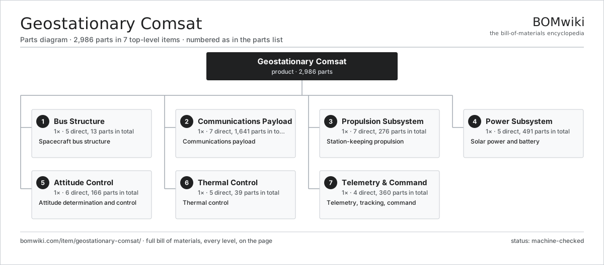
| # | Part | Qty | What it does |
|---|---|---|---|
| 1 | Bus Structure 5 parts | 1× | Spacecraft bus structure |
| 2 | Communications Payload 7 parts | 1× | Communications payload |
| 3 | Propulsion Subsystem 7 parts | 1× | Station-keeping propulsion |
| 4 | Power Subsystem 5 parts | 1× | Solar power and battery |
| 5 | Attitude Control 6 parts | 1× | Attitude determination and control |
| 6 | Thermal Control 5 parts | 1× | Thermal control |
| 7 | Telemetry & Command 4 parts | 1× | Telemetry, tracking, command |
3D model
No 3D model yet. Have a CAD file of this? Add a 3D model. STL renders right on this page; STEP, FreeCAD, and OpenSCAD sources are welcome too (openly licensed, like all 3D models on BOMwiki).
Build & assembly graph
expand / collapse · shared sub-assemblies converge · links to related products · est. labourTap an assembly to expand/collapse · tap a part to open it · use “Open page” for any node · drag to pan, scroll to zoom.
Bill of materials for Geostationary Comsat
7 top-level lines · 89 rows shown · 2,986 parts total · indented to 3 levels| # | Item / sub-assembly | Part no. | Qty/assy | Ext. qty | Parts | Type |
|---|---|---|---|---|---|---|
| 1 | Bus Structure 5 parts | geo-bus-structure | 1× | 1 | 13 | assembly |
| 1.1 | Central Cylinder | geo-central-cylinder | 1× | 1 | · | part |
| 1.2 | Shear Panel | geo-shear-panel | 4× | 4 | · | part |
| 1.3 | Equipment Panel | geo-equipment-panel | 6× | 6 | · | part |
| 1.4 | Separation Ring | geo-separation-ring | 1× | 1 | · | part |
| 1.5 | Fastener Set | fastener-set | 1× | 1 | · | part |
| 2 | Communications Payload 7 parts | geo-payload | 1× | 1 | 1,641 | assembly |
| 2.1 | Receive Antenna 3 parts | geo-receive-antenna | 2× | 2 | 6 | assembly |
| 2.1.1 | Shaped Reflector | geo-reflector | 1× | 2 | · | part |
| 2.1.2 | Feed Horn | geo-feed-horn | 4× | 8 | · | part |
| 2.1.3 | Antenna Boom | geo-antenna-boom | 1× | 2 | · | part |
| 2.2 | Transmit Antenna 3 parts | geo-transmit-antenna | 2× | 2 | 8 | assembly |
| 2.2.1 | Shaped Reflector | geo-reflector | 1× | 2 | · | part |
| 2.2.2 | Feed Horn | geo-feed-horn | 6× | 12 | · | part |
| 2.2.3 | Antenna Boom | geo-antenna-boom | 1× | 2 | · | part |
| 2.3 | Transponder 5 parts | geo-transponder | 24× | 24 | 64 | assembly |
| 2.3.1 | Low-Noise Amplifier | geo-lna | 1× | 24 | · | part |
| 2.3.2 | Downconverter | geo-downconverter | 1× | 24 | · | part |
| 2.3.3 | Channel Filter | geo-channel-filter | 1× | 24 | · | part |
| 2.3.4 | Bare PCB | pcb-bare | 1× | 24 | · | part |
| 2.3.5 | SMD Passive (R/C/L) | smd-passives | 60× | 1,440 | · | part |
| 2.4 | Input Multiplexer | geo-input-multiplexer | 2× | 2 | · | part |
| 2.5 | Output Multiplexer | geo-output-multiplexer | 2× | 2 | · | part |
| 2.6 | Traveling-Wave-Tube Amplifier 3 parts | geo-twta | 24× | 24 | 3 | assembly |
| 2.6.1 | Traveling-Wave Tube | geo-twt | 1× | 24 | · | part |
| 2.6.2 | Electronic Power Conditioner | geo-epc | 1× | 24 | · | part |
| 2.6.3 | TWTA Housing | geo-twta-housing | 1× | 24 | · | part |
| 2.7 | Waveguide Network | geo-waveguide | 1× | 1 | · | part |
| 3 | Propulsion Subsystem 7 parts | geo-propulsion | 1× | 1 | 276 | assembly |
| 3.1 | Apogee Engine | geo-apogee-engine | 1× | 1 | · | part |
| 3.2 | Ion Thruster 3 parts | geo-ion-thruster | 4× | 4 | 4 | assembly |
| 3.2.1 | Discharge Chamber | geo-discharge-chamber | 1× | 4 | · | part |
| 3.2.2 | Ion Grid Set | geo-grid-set | 1× | 4 | · | part |
| 3.2.3 | Hollow Cathode | geo-cathode | 2× | 8 | · | part |
| 3.3 | Xenon Tank | geo-xenon-tank | 2× | 2 | · | part |
| 3.4 | Chemical Tank | geo-chemical-tank | 2× | 2 | · | part |
| 3.5 | Power Processing Unit 3 parts | geo-ppu | 1× | 1 | 243 | assembly |
| 3.5.1 | Bare PCB | pcb-bare | 2× | 2 | · | part |
| 3.5.2 | Microcontroller | mcu | 1× | 1 | · | part |
| 3.5.3 | SMD Passive (R/C/L) | smd-passives | 240× | 240 | · | part |
| 3.6 | Propellant Valve | geo-prop-valve | 8× | 8 | · | part |
| 3.7 | Thruster Gimbal | geo-thruster-gimbal | 4× | 4 | · | part |
| 4 | Power Subsystem 5 parts | geo-power | 1× | 1 | 491 | assembly |
| 4.1 | Solar Wing 3 parts | geo-solar-wing | 2× | 2 | 10 | assembly |
| 4.1.1 | Solar Panel | geo-solar-panel | 5× | 10 | · | part |
| 4.1.2 | Panel Hinge | geo-panel-hinge | 4× | 8 | · | part |
| 4.1.3 | Array Yoke | geo-yoke | 1× | 2 | · | part |
| 4.2 | Solar-Array Drive | geo-sadm | 2× | 2 | · | part |
| 4.3 | Lithium Battery 3 parts | geo-battery | 1× | 1 | 125 | assembly |
| 4.3.1 | Space Li-ion Cell | geo-battery-cell | 32× | 32 | · | part |
| 4.3.2 | Battery Electronics 3 parts + deeper › | geo-battery-bms | 1× | 1 | 92 | assembly |
| 4.3.3 | Battery Housing | geo-battery-housing | 1× | 1 | · | part |
| 4.4 | Power Conditioning Unit 4 parts | geo-pcu | 1× | 1 | 343 | assembly |
| 4.4.1 | Bare PCB | pcb-bare | 2× | 2 | · | part |
| 4.4.2 | Microcontroller | mcu | 1× | 1 | · | part |
| 4.4.3 | Relay | relay | 20× | 20 | · | part |
| 4.4.4 | SMD Passive (R/C/L) | smd-passives | 320× | 320 | · | part |
| 4.5 | Wire Bundle | wire-bundle | 1× | 1 | · | part |
| 5 | Attitude Control 6 parts | geo-adcs | 1× | 1 | 166 | assembly |
| 5.1 | Momentum Wheel | geo-momentum-wheel | 4× | 4 | · | part |
| 5.2 | Earth Sensor | geo-earth-sensor | 2× | 2 | · | part |
| 5.3 | Sun Sensor | geo-sun-sensor | 4× | 4 | · | part |
| 5.4 | Star Tracker | geo-star-tracker | 2× | 2 | · | part |
| 5.5 | Gyro Unit | geo-gyro | 1× | 1 | · | part |
| 5.6 | ADCS Computer 3 parts | geo-adcs-computer | 1× | 1 | 153 | assembly |
| 5.6.1 | Bare PCB | pcb-bare | 1× | 1 | · | part |
| 5.6.2 | Microcontroller | mcu | 2× | 2 | · | part |
| 5.6.3 | SMD Passive (R/C/L) | smd-passives | 150× | 150 | · | part |
| 6 | Thermal Control 5 parts | geo-thermal | 1× | 1 | 39 | assembly |
| 6.1 | Radiator Panel | geo-radiator-panel | 2× | 2 | · | part |
| 6.2 | Heat Pipe | geo-heat-pipe | 12× | 12 | · | part |
| 6.3 | MLI Blanket | geo-mli-blanket | 1× | 1 | · | part |
| 6.4 | Heater | geo-heater | 12× | 12 | · | part |
| 6.5 | Thermostat | geo-thermostat | 12× | 12 | · | part |
| 7 | Telemetry & Command 4 parts | geo-tt-c | 1× | 1 | 360 | assembly |
| 7.1 | TT&C Transponder 4 parts | geo-tt-transponder | 1× | 1 | 103 | assembly |
| 7.1.1 | Bare PCB | pcb-bare | 1× | 1 | · | part |
| 7.1.2 | Microcontroller | mcu | 1× | 1 | · | part |
| 7.1.3 | TT&C RF Module | geo-tt-rf | 1× | 1 | · | part |
| 7.1.4 | SMD Passive (R/C/L) | smd-passives | 100× | 100 | · | part |
| 7.2 | Omni Antenna | geo-omni-antenna | 2× | 2 | · | part |
| 7.3 | Onboard Computer 3 parts | geo-obc | 1× | 1 | 183 | assembly |
| 7.3.1 | Bare PCB | pcb-bare | 1× | 1 | · | part |
| 7.3.2 | Microcontroller | mcu | 2× | 2 | · | part |
| 7.3.3 | SMD Passive (R/C/L) | smd-passives | 180× | 180 | · | part |
| 7.4 | Command Decoder 3 parts | geo-rwa-driver | 1× | 1 | 72 | assembly |
| 7.4.1 | Bare PCB | pcb-bare | 1× | 1 | · | part |
| 7.4.2 | Microcontroller | mcu | 1× | 1 | · | part |
| 7.4.3 | SMD Passive (R/C/L) | smd-passives | 70× | 70 | · | part |
Sourcing: possible vendors
Browse the supplier directory → Prices, MOQ, and lead times are algorithmic estimates, not quotes, and not claims about these companies. Company mappings are curated by keyword; est. price band $50k–$500M. How estimates work| Vendor | HQ | Specialty | MOQ | Lead time |
|---|---|---|---|---|
|
🇺🇸SpaceX
spacex.com ↗
|
Hawthorne, US | Launch & spacecraft | made to order | 52–104 wks |
| northropgrumman.com ↗ | Falls Church, US | Space & defense | made to order | 52–104 wks |
|
🇫🇷Airbus
airbus.com ↗
|
Toulouse, FR | Aerospace OEM | made to order | 52–104 wks |
| rocketlabusa.com ↗ | Long Beach, US | Launch & spacecraft | made to order | 52–104 wks |
| thalesaleniaspace.com ↗ | Cannes, FR | Satellites | made to order | 52–104 wks |
887-word article