Planetary Lander
ProductOverview
A planetary lander is a spacecraft built to do one hard thing well: arrive at the surface of a moon or planet intact and upright, then keep working. Reaching the surface is not the same problem as reaching orbit. The vehicle must shed all of its orbital velocity, sense how far it is from a surface it has never touched, pick a spot free of boulders and slopes, and set down gently enough that nothing breaks. Everything in the design serves that descent and the surface mission that follows.
The vehicle is organized around a stiff Primary Structure that carries every other subsystem. Hung on it are the Descent Propulsion that brakes the fall, four Landing Leg legs that absorb the touchdown, the Guidance & Control that flies the trajectory, a Power Subsystem subsystem, the Thermal Control control that keeps electronics alive through the temperature swings, the Communications link back to Earth, and the Science Payload that does the science once the dust settles.
Primary structure
The Primary Structure is a load path more than a box. A central Thrust Tube of carbon fiber takes the concentrated thrust of the descent engines and spreads it into a stack of Honeycomb Deck Panel honeycomb decks. The decks are light aluminum-honeycomb sandwiches that give large flat areas for mounting tanks, avionics, and instruments. A web of titanium Truss Strut members ties the decks and propellant tanks into a frame stiff enough to survive launch vibration without flexing into its own equipment. At four points, Leg Bracket fittings carry the landing loads from the legs back into this frame.
Descent propulsion
The Descent Propulsion turns orbital speed into a controlled fall. Four Descent Engine units burn storable bipropellant, fuel and oxidizer that stay liquid at spacecraft temperatures and ignite on contact, so there is no ignition system to fail at the worst moment. Each engine has a regeneratively cooled Thrust Chamber, a fine Injector to mix the propellants, fast Engine Valve units to start and stop the flow, and a pair of Gimbal Actuator units that tilt the thrust to steer. Because the lander gets lighter as it burns propellant and must hover near touchdown, the engines throttle deeply rather than running at one fixed level.
Propellant comes from a Fuel Tank and an Oxidizer Tank pushed out by helium from a Helium Tank through a Pressure Regulator. A network of Propellant Valve units and a welded Propellant Line Set manifold routes the flow. Twelve small RCS Thruster units handle fine attitude during the coast and descent, when the main engines are off or too coarse for small corrections.
Landing gear and touchdown
Each Landing Leg leg is an energy-absorbing machine. A telescoping Primary Strut carries the vertical impact, and inside it a Crush Cartridge of aluminum honeycomb crushes at a known force, converting the kinetic energy of touchdown into permanent deformation instead of a bounce. Two Secondary Strut braces stabilize the leg against sideways drift, and a wide Footpad keeps the leg from punching into loose regolith. The legs ride folded against the body through launch and cruise; a Deploy Mechanism with a spring, a release actuator, and lock pins swings them out and latches them rigid before landing.
Guidance, power, and thermal
The Guidance & Control subsystem is what separates a soft landing from a crater. A Flight Computer built around a radiation-hardened processor fuses data from the Inertial Measurement Unit, a Landing Radar measuring speed and altitude, a hazard Hazard Lidar that maps the ground for boulders, and Terrain Camera units that match the view to a stored map. A Star Tracker and Reaction Wheel set hold attitude during the long cruise before descent begins.
Power comes from the Power Subsystem subsystem: deployable Solar Array wings charge a lithium Lithium Battery, and a Power Control Unit distributes regulated buses. The Thermal Control subsystem matters more than it looks, because surface temperatures swing by hundreds of degrees between day and night. An MLI Blanket insulates the body, Radiator Panel panels dump waste heat, Heat Pipe runs carry it there, and Survival Heater units cycled by thermostats keep cold-sensitive boxes above their limits through the dark.
Communications and payload
The Communications subsystem keeps the lander in contact. A Transponder drives a steerable High-Gain Antenna dish for high-rate science return and a pair of Low-Gain Antenna antennas for low-rate, wide-angle contact when the dish is not pointed. The Science Payload is the mission's purpose: Surface Camera units document the site, a Spectrometer reads surface composition, an Environment Package logs radiation and dust, and a Sample Arm with a scoop gathers material for analysis. Variants range from small commercial lunar landers carrying a few instruments to large interplanetary landers that double as rover delivery platforms, but the descent problem and its hardware stay the same across all of them.
Planetary Lander parts and their functions
8 top-level parts · 1,109 parts in total · full bill of materials below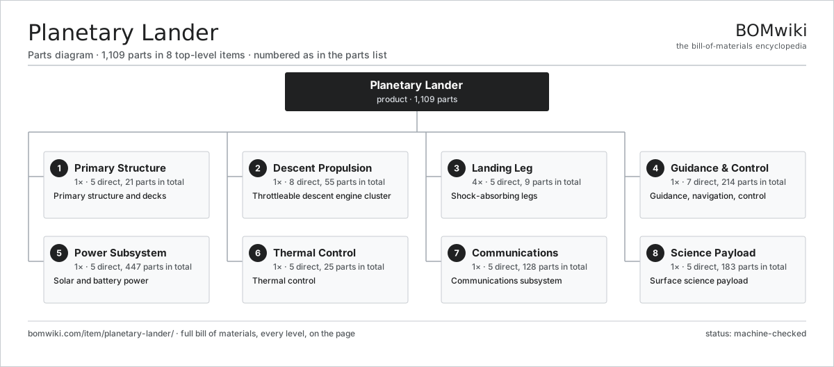
| # | Part | Qty | What it does |
|---|---|---|---|
| 1 | Primary Structure 5 parts | 1× | Primary structure and decks |
| 2 | Descent Propulsion 8 parts | 1× | Throttleable descent engine cluster |
| 3 | Landing Leg 5 parts | 4× | Shock-absorbing legs |
| 4 | Guidance & Control 7 parts | 1× | Guidance, navigation, control |
| 5 | Power Subsystem 5 parts | 1× | Solar and battery power |
| 6 | Thermal Control 5 parts | 1× | Thermal control |
| 7 | Communications 5 parts | 1× | Communications subsystem |
| 8 | Science Payload 5 parts | 1× | Surface science payload |
3D model
No 3D model yet. Have a CAD file of this? Add a 3D model. STL renders right on this page; STEP, FreeCAD, and OpenSCAD sources are welcome too (openly licensed, like all 3D models on BOMwiki).
Build & assembly graph
expand / collapse · shared sub-assemblies converge · links to related products · est. labourTap an assembly to expand/collapse · tap a part to open it · use “Open page” for any node · drag to pan, scroll to zoom.
Bill of materials for Planetary Lander
8 top-level lines · 88 rows shown · 1,109 parts total · indented to 3 levels| # | Item / sub-assembly | Part no. | Qty/assy | Ext. qty | Parts | Type |
|---|---|---|---|---|---|---|
| 1 | Primary Structure 5 parts | plnd-structure | 1× | 1 | 21 | assembly |
| 1.1 | Thrust Tube | plnd-thrust-tube | 1× | 1 | · | part |
| 1.2 | Honeycomb Deck Panel | plnd-deck-panel | 3× | 3 | · | part |
| 1.3 | Truss Strut | plnd-strut | 12× | 12 | · | part |
| 1.4 | Leg Bracket | plnd-leg-bracket | 4× | 4 | · | part |
| 1.5 | Fastener Set | fastener-set | 1× | 1 | · | part |
| 2 | Descent Propulsion 8 parts | plnd-descent-propulsion | 1× | 1 | 55 | assembly |
| 2.1 | Descent Engine 5 parts | plnd-descent-engine | 4× | 4 | 7 | assembly |
| 2.1.1 | Thrust Chamber | plnd-thrust-chamber | 1× | 4 | · | part |
| 2.1.2 | Injector | plnd-injector | 1× | 4 | · | part |
| 2.1.3 | Engine Valve | plnd-engine-valve | 2× | 8 | · | part |
| 2.1.4 | Gimbal Actuator | plnd-gimbal-actuator | 2× | 8 | · | part |
| 2.1.5 | Igniter | plnd-igniter | 1× | 4 | · | part |
| 2.2 | RCS Thruster | plnd-rcs-thruster | 12× | 12 | · | part |
| 2.3 | Fuel Tank | plnd-fuel-tank | 1× | 1 | · | part |
| 2.4 | Oxidizer Tank | plnd-oxidizer-tank | 1× | 1 | · | part |
| 2.5 | Helium Tank | plnd-helium-tank | 2× | 2 | · | part |
| 2.6 | Propellant Valve | plnd-prop-valve | 8× | 8 | · | part |
| 2.7 | Propellant Line Set | plnd-prop-line | 1× | 1 | · | part |
| 2.8 | Pressure Regulator | plnd-pressure-regulator | 2× | 2 | · | part |
| 3 | Landing Leg 5 parts | plnd-landing-gear | 4× | 4 | 9 | assembly |
| 3.1 | Primary Strut | plnd-primary-strut | 1× | 4 | · | part |
| 3.2 | Secondary Strut | plnd-secondary-strut | 2× | 8 | · | part |
| 3.3 | Crush Cartridge | plnd-crush-cartridge | 1× | 4 | · | part |
| 3.4 | Footpad | plnd-footpad | 1× | 4 | · | part |
| 3.5 | Deploy Mechanism 3 parts | plnd-deploy-mechanism | 1× | 4 | 4 | assembly |
| 3.5.1 | Deploy Spring | plnd-deploy-spring | 1× | 4 | · | part |
| 3.5.2 | Release Actuator | plnd-release-actuator | 1× | 4 | · | part |
| 3.5.3 | Lock Pin | plnd-lock-pin | 2× | 8 | · | part |
| 4 | Guidance & Control 7 parts | plnd-gnc | 1× | 1 | 214 | assembly |
| 4.1 | Flight Computer 4 parts | plnd-flight-computer | 1× | 1 | 204 | assembly |
| 4.1.1 | Bare PCB | pcb-bare | 1× | 1 | · | part |
| 4.1.2 | Microcontroller | mcu | 2× | 2 | · | part |
| 4.1.3 | Radiation-Hardened Processor | plnd-rad-processor | 1× | 1 | · | part |
| 4.1.4 | SMD Passive (R/C/L) | smd-passives | 200× | 200 | · | part |
| 4.2 | Inertial Measurement Unit | plnd-imu | 1× | 1 | · | part |
| 4.3 | Landing Radar | plnd-landing-radar | 1× | 1 | · | part |
| 4.4 | Hazard Lidar | plnd-lidar | 1× | 1 | · | part |
| 4.5 | Terrain Camera | plnd-terrain-camera | 2× | 2 | · | part |
| 4.6 | Star Tracker | plnd-star-tracker | 1× | 1 | · | part |
| 4.7 | Reaction Wheel | plnd-reaction-wheel | 4× | 4 | · | part |
| 5 | Power Subsystem 5 parts | plnd-power | 1× | 1 | 447 | assembly |
| 5.1 | Solar Array 3 parts | plnd-solar-array | 2× | 2 | 9 | assembly |
| 5.1.1 | Solar Panel | plnd-solar-panel | 4× | 8 | · | part |
| 5.1.2 | Array Hinge | plnd-array-hinge | 3× | 6 | · | part |
| 5.1.3 | Deploy Spring | plnd-deploy-spring | 2× | 4 | · | part |
| 5.2 | Lithium Battery 3 parts | plnd-battery | 1× | 1 | 107 | assembly |
| 5.2.1 | Space Li-ion Cell | plnd-battery-cell | 24× | 24 | · | part |
| 5.2.2 | Battery Management Unit 3 parts + deeper › | plnd-bms | 1× | 1 | 82 | assembly |
| 5.2.3 | Battery Housing | plnd-battery-housing | 1× | 1 | · | part |
| 5.3 | Power Control Unit 4 parts | plnd-pcdu | 1× | 1 | 319 | assembly |
| 5.3.1 | Bare PCB | pcb-bare | 2× | 2 | · | part |
| 5.3.2 | Microcontroller | mcu | 1× | 1 | · | part |
| 5.3.3 | Relay | relay | 16× | 16 | · | part |
| 5.3.4 | SMD Passive (R/C/L) | smd-passives | 300× | 300 | · | part |
| 5.4 | Array Drive | plnd-array-drive | 2× | 2 | · | part |
| 5.5 | Wire Bundle | wire-bundle | 1× | 1 | · | part |
| 6 | Thermal Control 5 parts | plnd-thermal | 1× | 1 | 25 | assembly |
| 6.1 | MLI Blanket | plnd-mli-blanket | 1× | 1 | · | part |
| 6.2 | Radiator Panel | plnd-radiator | 2× | 2 | · | part |
| 6.3 | Heat Pipe | plnd-heat-pipe | 6× | 6 | · | part |
| 6.4 | Survival Heater | plnd-survival-heater | 8× | 8 | · | part |
| 6.5 | Thermostat | plnd-thermostat | 8× | 8 | · | part |
| 7 | Communications 5 parts | plnd-comms | 1× | 1 | 128 | assembly |
| 7.1 | Transponder 4 parts | plnd-transponder | 1× | 1 | 123 | assembly |
| 7.1.1 | Bare PCB | pcb-bare | 1× | 1 | · | part |
| 7.1.2 | Microcontroller | mcu | 1× | 1 | · | part |
| 7.1.3 | RF Module | plnd-rf-module | 1× | 1 | · | part |
| 7.1.4 | SMD Passive (R/C/L) | smd-passives | 120× | 120 | · | part |
| 7.2 | High-Gain Antenna | plnd-hga | 1× | 1 | · | part |
| 7.3 | Low-Gain Antenna | plnd-lga | 2× | 2 | · | part |
| 7.4 | Power Amplifier | plnd-tx-amplifier | 1× | 1 | · | part |
| 7.5 | Antenna Gimbal | plnd-antenna-gimbal | 1× | 1 | · | part |
| 8 | Science Payload 5 parts | plnd-payload | 1× | 1 | 183 | assembly |
| 8.1 | Surface Camera | plnd-surface-camera | 2× | 2 | · | part |
| 8.2 | Spectrometer | plnd-spectrometer | 1× | 1 | · | part |
| 8.3 | Environment Package 3 parts | plnd-env-package | 1× | 1 | 3 | assembly |
| 8.3.1 | Pressure Sensor | pressure-sensor | 1× | 1 | · | part |
| 8.3.2 | Radiation Monitor | plnd-radiation-monitor | 1× | 1 | · | part |
| 8.3.3 | Dust Sensor | plnd-dust-sensor | 1× | 1 | · | part |
| 8.4 | Sample Arm 3 parts | plnd-sample-arm | 1× | 1 | 75 | assembly |
| 8.4.1 | Servo Motor 4 parts + deeper › | servo-motor | 3× | 3 | 24 | assembly |
| 8.4.2 | Sample Scoop | plnd-scoop | 1× | 1 | · | part |
| 8.4.3 | Arm Link | plnd-arm-link | 2× | 2 | · | part |
| 8.5 | Payload Computer 3 parts | plnd-payload-computer | 1× | 1 | 102 | assembly |
| 8.5.1 | Bare PCB | pcb-bare | 1× | 1 | · | part |
| 8.5.2 | Microcontroller | mcu | 1× | 1 | · | part |
| 8.5.3 | SMD Passive (R/C/L) | smd-passives | 100× | 100 | · | part |
Related products
same domain, ranked by shared parts Cargo Resupply Spacecraft
574 parts · shares 12 with this page
Cargo Resupply Spacecraft
574 parts · shares 12 with this page
 Crewed Space Capsule
7,222 parts · shares 12 with this page
Crewed Space Capsule
7,222 parts · shares 12 with this page
 GPS Navigation Satellite
2,640 parts · shares 12 with this page
GPS Navigation Satellite
2,640 parts · shares 12 with this page
 Ion Thruster
880 parts · shares 12 with this page
Ion Thruster
880 parts · shares 12 with this page
 Lunar Lander
1,803 parts · shares 12 with this page
Lunar Lander
1,803 parts · shares 12 with this page
 Planetary Rover
1,805 parts · shares 12 with this page
Planetary Rover
1,805 parts · shares 12 with this page
Sourcing: possible vendors
Browse the supplier directory → Prices, MOQ, and lead times are algorithmic estimates, not quotes, and not claims about these companies. Company mappings are curated by keyword; est. price band $50k–$500M. How estimates work| Vendor | HQ | Specialty | MOQ | Lead time |
|---|---|---|---|---|
|
🇺🇸SpaceX
spacex.com ↗
|
Hawthorne, US | Launch & spacecraft | made to order | 52–104 wks |
| northropgrumman.com ↗ | Falls Church, US | Space & defense | made to order | 52–104 wks |
|
🇫🇷Airbus
airbus.com ↗
|
Toulouse, FR | Aerospace OEM | made to order | 52–104 wks |
| rocketlabusa.com ↗ | Long Beach, US | Launch & spacecraft | made to order | 52–104 wks |
| thalesaleniaspace.com ↗ | Cannes, FR | Satellites | made to order | 52–104 wks |
848-word article