Crewed Space Capsule
ProductOverview
A crewed space capsule carries astronauts from the launch pad to orbit, supports them during the mission, and returns them safely through the atmosphere to a water or ground landing. It is the most safety-critical pressurized vehicle in common production: a single hull failure, a heat shield breach, or a parachute that fails to open is unsurvivable. Every subsystem is built with redundancy, and the whole vehicle is qualified to keep the crew alive through a launch abort at any point in ascent.
The capsule described here follows the modern blunt-body class flown by Crew Dragon, Orion, and Soyuz: a truncated cone roughly 4 m across at its base, with a habitable pressure vessel for the crew and a service section carrying propellant, radiators, and solar power. It launches atop an expendable or reusable booster, separates after second-stage cutoff, maneuvers and docks to a station, then later deorbits, sheds its service section, and reenters protected by an ablative heat shield. Descent is staged through drogue and main parachutes to a survivable landing.
Pressure vessel and structure
The primary structure is a sealed cabin that holds about one atmosphere of breathable gas against the vacuum of space. The crew module shell is built from machined aluminium-lithium hull panels joined by friction-stir welds and stiffened with isogrid rings, a layout that gives high strength at low mass. Forward and aft pressure bulkheads close the cabin, and the load from launch and landing is carried into the backshell support frame.
Crew see out through cabin windows made of triple-pane fused silica in titanium retainer frames, each pane separately pressure-rated so a single crack is not a leak path. The side hatch seals on a silicone seal driven by six latches and a motorized actuator, with a pressure sensor confirming the seal before launch. The forward docking adapter mates to a station using a soft-capture ring and petals that absorb closing energy, then twelve hard-capture latches pull the interface airtight against its seals.
Thermal protection
Reentry from low Earth orbit converts the vehicle's 7.8 km/s of velocity into heat. The thermal protection system keeps that heat outside the cabin. The forward heat shield is the hottest part, reaching roughly 1650 C at peak heating. It is built from PICA ablator blocks bonded into a honeycomb on a composite carrier structure; the ablator chars and sheds material, carrying energy away rather than conducting it inward. The cooler conical sides are covered with silica backshell tiles, held by standoff hardware with ceramic isolators so heat does not bridge into the structure. On orbit, multi-layer insulation blankets handle the gentler thermal swings between sunlight and shadow.
Propulsion and reaction control
The propulsion system runs on storable hypergolic propellants: nitrogen tetroxide and monomethylhydrazine, which ignite on contact and need no separate ignition source. MMH and NTO tanks use elastomer diaphragms to feed propellant in zero gravity, pressurized by helium from a carbon-overwrapped tank held near 310 bar and stepped down by regulators. Service thrusters perform orbit maneuvers, while powerful launch abort thrusters can pull the capsule clear of a failing booster in under two seconds. Flow is controlled by isolation valves through a network of stainless feed lines.
Fine attitude control comes from the reaction control system, four thruster pods of small attitude thrusters that point the vehicle for docking and hold it stable through reentry.
Avionics and GNC
The avionics suite flies the vehicle. Three flight computers, each built on a radiation-hardened CPU, run guidance, navigation, and control in triple modular redundancy, with voting logic discarding any computer that disagrees. Position and attitude come from redundant inertial measurement units, optical star trackers that match star fields to an onboard catalog, and GPS receivers in orbit. A rendezvous lidar provides relative range and bearing for the final approach to a station. The crew monitor and command the vehicle through touchscreen glass displays, all tied together over a redundant data bus.
Life support and power
The environmental control and life support system keeps the cabin habitable. CO2 scrubbers pull exhaled carbon dioxide from the air using amine sorbent beds, oxygen tanks replace what the crew consume, and circulation fans keep the atmosphere mixed so no stagnant pockets form in weightlessness. A pumped coolant loop with a condensing heat exchanger and radiator panels removes metabolic and equipment heat and controls humidity, while pressure regulators hold cabin pressure and an atmosphere sensor pack watches oxygen, carbon dioxide, and humidity continuously.
Electrical power comes from the power system. Body-mounted solar arrays of triple-junction cells charge lithium-ion battery modules, and a power distribution unit switches and protects the 28 VDC buses feeding every load through the power harness.
Recovery
After the deorbit burn and reentry, the recovery system slows the capsule for landing. Two drogue parachutes deploy first to stabilize and decelerate the vehicle while it is still moving fast, fired clear by gas mortars. The drogues then release four main ringsail canopies that bring descent down to about 7 m/s. For a water landing, the flotation system inflates bags that keep the capsule upright and afloat; a ground-landing variant instead uses energy-absorbing landing legs with crushable cartridges to soften touchdown.
Crew accommodations and variants
Inside, the crew accommodations hold the astronauts safely through high-load phases. Each seat is a contoured couch with a custom liner on stroking shock attenuators and a five-point restraint. A suit interface panel connects each pressure suit to cabin air, cooling, and communications, so the crew stay protected if cabin pressure is ever lost. Manual override is available through the control panel with hand controllers and a switch panel, and cargo rides in restrained stowage.
The same airframe supports several mission types. A crew of four is standard for station rotation flights of up to about 210 days docked, while a denser seating layout carries up to seven for short free-flight missions. Cargo variants remove the seats and life support to deliver pressurized supplies and return experiments to the ground, reusing the structure, heat shield, and recovery hardware unchanged.
Crewed Space Capsule parts and their functions
9 top-level parts · 7,222 parts in total · full bill of materials below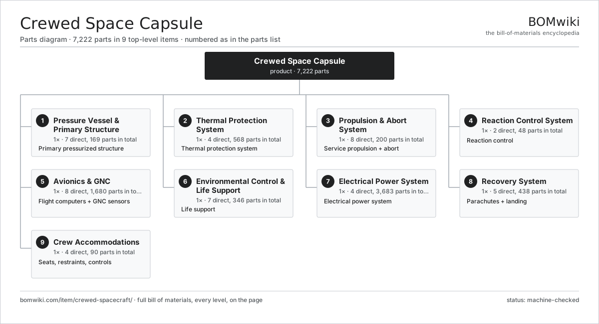
| # | Part | Qty | What it does |
|---|---|---|---|
| 1 | Pressure Vessel & Primary Structure 7 parts | 1× | Primary pressurized structure |
| 2 | Thermal Protection System 4 parts | 1× | Thermal protection system |
| 3 | Propulsion & Abort System 8 parts | 1× | Service propulsion + abort |
| 4 | Reaction Control System 2 parts | 1× | Reaction control |
| 5 | Avionics & GNC 8 parts | 1× | Flight computers + GNC sensors |
| 6 | Environmental Control & Life Support 7 parts | 1× | Life support |
| 7 | Electrical Power System 4 parts | 1× | Electrical power system |
| 8 | Recovery System 5 parts | 1× | Parachutes + landing |
| 9 | Crew Accommodations 4 parts | 1× | Seats, restraints, controls |
3D model
No 3D model yet. Have a CAD file of this? Add a 3D model. STL renders right on this page; STEP, FreeCAD, and OpenSCAD sources are welcome too (openly licensed, like all 3D models on BOMwiki).
Build & assembly graph
expand / collapse · shared sub-assemblies converge · links to related products · est. labourTap an assembly to expand/collapse · tap a part to open it · use “Open page” for any node · drag to pan, scroll to zoom.
Bill of materials for Crewed Space Capsule
9 top-level lines · 209 rows shown · 7,222 parts total · indented to 3 levels| # | Item / sub-assembly | Part no. | Qty/assy | Ext. qty | Parts | Type |
|---|---|---|---|---|---|---|
| 1 | Pressure Vessel & Primary Structure 7 parts | crewed-spacecraft-pressure-vessel | 1× | 1 | 169 | assembly |
| 1.1 | Crew Module Shell 3 parts | crewed-spacecraft-crew-shell | 1× | 1 | 11 | assembly |
| 1.1.1 | Aluminium-Lithium Hull Panel | crewed-spacecraft-hull-panel | 6× | 6 | · | part |
| 1.1.2 | Isogrid Stiffening Ring | crewed-spacecraft-isogrid-ring | 4× | 4 | · | part |
| 1.1.3 | Friction-Stir Weld Seam | crewed-spacecraft-weld-seam | 1× | 1 | · | part |
| 1.2 | Pressure Bulkhead | crewed-spacecraft-pressure-bulkhead | 2× | 2 | · | part |
| 1.3 | Cabin Window Assembly 3 parts | crewed-spacecraft-window-assembly | 4× | 4 | 6 | assembly |
| 1.3.1 | Fused Silica Window Pane | crewed-spacecraft-window-pane | 3× | 12 | · | part |
| 1.3.2 | Window Retainer Frame | crewed-spacecraft-window-frame | 1× | 4 | · | part |
| 1.3.3 | O-Ring Set | oring-set | 2× | 8 | · | part |
| 1.4 | Side Hatch Assembly 5 parts | crewed-spacecraft-hatch | 1× | 1 | 35 | assembly |
| 1.4.1 | Hatch Door | crewed-spacecraft-hatch-door | 1× | 1 | · | part |
| 1.4.2 | Hatch Silicone Seal | crewed-spacecraft-hatch-seal | 1× | 1 | · | part |
| 1.4.3 | Hatch Latch | crewed-spacecraft-hatch-latch | 6× | 6 | · | part |
| 1.4.4 | Hatch Drive Actuator 3 parts + deeper › | crewed-spacecraft-hatch-actuator | 1× | 1 | 26 | assembly |
| 1.4.5 | Pressure Sensor | pressure-sensor | 1× | 1 | · | part |
| 1.5 | Docking Adapter (IDA) 7 parts | crewed-spacecraft-docking-adapter | 1× | 1 | 95 | assembly |
| 1.5.1 | Soft-Capture Docking Ring | crewed-spacecraft-docking-ring | 1× | 1 | · | part |
| 1.5.2 | Capture Petal | crewed-spacecraft-soft-capture-petal | 3× | 3 | · | part |
| 1.5.3 | Hard-Capture Latch | crewed-spacecraft-capture-latch | 12× | 12 | · | part |
| 1.5.4 | Docking Interface Seal | crewed-spacecraft-docking-seal | 2× | 2 | · | part |
| 1.5.5 | Linear Guide Rail | linear-guide | 3× | 3 | · | part |
| 1.5.6 | Servo Motor 4 parts + deeper › | servo-motor | 3× | 3 | 24 | assembly |
| 1.5.7 | Pressure Sensor | pressure-sensor | 2× | 2 | · | part |
| 1.6 | Backshell Support Frame | crewed-spacecraft-backshell-frame | 1× | 1 | · | part |
| 1.7 | Fastener Set | fastener-set | 1× | 1 | · | part |
| 2 | Thermal Protection System 4 parts | crewed-spacecraft-tps | 1× | 1 | 568 | assembly |
| 2.1 | Ablative Heat Shield 4 parts | crewed-spacecraft-heat-shield | 1× | 1 | 243 | assembly |
| 2.1.1 | PICA Ablator Block | crewed-spacecraft-ablator-block | 240× | 240 | · | part |
| 2.1.2 | Heat Shield Carrier Structure | crewed-spacecraft-shield-carrier | 1× | 1 | · | part |
| 2.1.3 | Shield Gap Filler | crewed-spacecraft-shield-gap-filler | 1× | 1 | · | part |
| 2.1.4 | Fastener Set | fastener-set | 1× | 1 | · | part |
| 2.2 | Backshell TPS Tile | crewed-spacecraft-backshell-tile | 180× | 180 | · | part |
| 2.3 | TPS Attachment Hardware 3 parts | crewed-spacecraft-tps-attach | 1× | 1 | 121 | assembly |
| 2.3.1 | TPS Standoff Bracket | crewed-spacecraft-standoff-bracket | 60× | 60 | · | part |
| 2.3.2 | Fastener Set | fastener-set | 1× | 1 | · | part |
| 2.3.3 | Thermal Isolator Washer | crewed-spacecraft-thermal-isolator | 60× | 60 | · | part |
| 2.4 | Multi-Layer Insulation Blanket | crewed-spacecraft-thermal-blanket | 24× | 24 | · | part |
| 3 | Propulsion & Abort System 8 parts | crewed-spacecraft-propulsion | 1× | 1 | 200 | assembly |
| 3.1 | Launch Abort Thruster (SuperDraco-class) 5 parts | crewed-spacecraft-abort-thruster | 8× | 8 | 7 | assembly |
| 3.1.1 | Regenerative Thrust Chamber | crewed-spacecraft-thrust-chamber | 1× | 8 | · | part |
| 3.1.2 | Coaxial Propellant Injector | crewed-spacecraft-injector | 1× | 8 | · | part |
| 3.1.3 | Radiatively-Cooled Nozzle | crewed-spacecraft-nozzle | 1× | 8 | · | part |
| 3.1.4 | Propellant Isolation Valve | crewed-spacecraft-prop-valve | 2× | 16 | · | part |
| 3.1.5 | Pressure Sensor | pressure-sensor | 2× | 16 | · | part |
| 3.2 | Service Maneuvering Thruster (Draco-class) 4 parts | crewed-spacecraft-service-thruster | 4× | 4 | 5 | assembly |
| 3.2.1 | Regenerative Thrust Chamber | crewed-spacecraft-thrust-chamber | 1× | 4 | · | part |
| 3.2.2 | Coaxial Propellant Injector | crewed-spacecraft-injector | 1× | 4 | · | part |
| 3.2.3 | Radiatively-Cooled Nozzle | crewed-spacecraft-nozzle | 1× | 4 | · | part |
| 3.2.4 | Propellant Isolation Valve | crewed-spacecraft-prop-valve | 2× | 8 | · | part |
| 3.3 | MMH Fuel Tank 4 parts | crewed-spacecraft-fuel-tank | 2× | 2 | 5 | assembly |
| 3.3.1 | Titanium Tank Shell | crewed-spacecraft-tank-shell | 1× | 2 | · | part |
| 3.3.2 | AF-E Elastomer Diaphragm | crewed-spacecraft-tank-diaphragm | 1× | 2 | · | part |
| 3.3.3 | Propellant Isolation Valve | crewed-spacecraft-prop-valve | 2× | 4 | · | part |
| 3.3.4 | Pressure Sensor | pressure-sensor | 1× | 2 | · | part |
| 3.4 | NTO Oxidizer Tank 4 parts | crewed-spacecraft-oxidizer-tank | 2× | 2 | 5 | assembly |
| 3.4.1 | Titanium Tank Shell | crewed-spacecraft-tank-shell | 1× | 2 | · | part |
| 3.4.2 | AF-E Elastomer Diaphragm | crewed-spacecraft-tank-diaphragm | 1× | 2 | · | part |
| 3.4.3 | Propellant Isolation Valve | crewed-spacecraft-prop-valve | 2× | 4 | · | part |
| 3.4.4 | Pressure Sensor | pressure-sensor | 1× | 2 | · | part |
| 3.5 | Helium Pressurant Tank (COPV) 4 parts | crewed-spacecraft-helium-tank | 2× | 2 | 4 | assembly |
| 3.5.1 | COPV Titanium Liner | crewed-spacecraft-copv-liner | 1× | 2 | · | part |
| 3.5.2 | Carbon-Fibre Overwrap | crewed-spacecraft-copv-overwrap | 1× | 2 | · | part |
| 3.5.3 | Pressure Regulator | crewed-spacecraft-pressure-regulator | 1× | 2 | · | part |
| 3.5.4 | Pressure Sensor | pressure-sensor | 1× | 2 | · | part |
| 3.6 | Propellant Isolation Valve | crewed-spacecraft-prop-valve | 16× | 16 | · | part |
| 3.7 | Pressure Regulator | crewed-spacecraft-pressure-regulator | 4× | 4 | · | part |
| 3.8 | Propellant Feed Lines & Manifold 3 parts | crewed-spacecraft-prop-line | 1× | 1 | 76 | assembly |
| 3.8.1 | Stainless Feed Tube | crewed-spacecraft-feed-tube | 24× | 24 | · | part |
| 3.8.2 | AN Flare Fitting | crewed-spacecraft-line-fitting | 48× | 48 | · | part |
| 3.8.3 | O-Ring Set | oring-set | 4× | 4 | · | part |
| 4 | Reaction Control System 2 parts | crewed-spacecraft-rcs | 1× | 1 | 48 | assembly |
| 4.1 | RCS Thruster Pod 4 parts | crewed-spacecraft-rcs-pod | 4× | 4 | 10 | assembly |
| 4.1.1 | RCS Attitude Thruster | crewed-spacecraft-rcs-thruster | 4× | 16 | · | part |
| 4.1.2 | Propellant Isolation Valve | crewed-spacecraft-prop-valve | 4× | 16 | · | part |
| 4.1.3 | Pressure Sensor | pressure-sensor | 1× | 4 | · | part |
| 4.1.4 | RCS Pod Mounting Bracket | crewed-spacecraft-pod-bracket | 1× | 4 | · | part |
| 4.2 | Propellant Isolation Valve | crewed-spacecraft-prop-valve | 8× | 8 | · | part |
| 5 | Avionics & GNC 8 parts | crewed-spacecraft-avionics | 1× | 1 | 1,680 | assembly |
| 5.1 | Flight Computer 6 parts | crewed-spacecraft-flight-computer | 3× | 3 | 418 | assembly |
| 5.1.1 | Bare PCB | pcb-bare | 2× | 6 | · | part |
| 5.1.2 | Radiation-Hardened CPU (RAD750-class) | crewed-spacecraft-radhard-cpu | 1× | 3 | · | part |
| 5.1.3 | Microcontroller | mcu | 2× | 6 | · | part |
| 5.1.4 | SMD Passive (R/C/L) | smd-passives | 400× | 1,200 | · | part |
| 5.1.5 | Connector | connector | 12× | 36 | · | part |
| 5.1.6 | Watchdog & Voting Logic | crewed-spacecraft-watchdog | 1× | 3 | · | part |
| 5.2 | IMU (6-axis) | imu | 2× | 2 | · | part |
| 5.3 | Star Tracker 4 parts | crewed-spacecraft-star-tracker | 2× | 2 | 6 | assembly |
| 5.3.1 | Camera Module 3 parts + deeper › | camera-module | 1× | 2 | 3 | assembly |
| 5.3.2 | Stray-Light Baffle | crewed-spacecraft-baffle | 1× | 2 | · | part |
| 5.3.3 | Bare PCB | pcb-bare | 1× | 2 | · | part |
| 5.3.4 | Microcontroller | mcu | 1× | 2 | · | part |
| 5.4 | GPS Module | gps-module | 2× | 2 | · | part |
| 5.5 | Avionics Data Bus & I/O 4 parts | crewed-spacecraft-data-bus | 1× | 1 | 33 | assembly |
| 5.5.1 | Bare PCB | pcb-bare | 2× | 2 | · | part |
| 5.5.2 | MIL-STD-1553 Transceiver | crewed-spacecraft-bus-transceiver | 6× | 6 | · | part |
| 5.5.3 | Connector | connector | 24× | 24 | · | part |
| 5.5.4 | Wire Bundle | wire-bundle | 1× | 1 | · | part |
| 5.6 | Cockpit Glass Display 3 parts | crewed-spacecraft-cockpit-display | 3× | 3 | 124 | assembly |
| 5.6.1 | LCD Panel | lcd-panel | 1× | 3 | · | part |
| 5.6.2 | Display Controller Board 3 parts + deeper › | crewed-spacecraft-display-controller | 1× | 3 | 122 | assembly |
| 5.6.3 | Display Cover Glass | crewed-spacecraft-cover-glass | 1× | 3 | · | part |
| 5.7 | Rendezvous LIDAR Sensor 4 parts | crewed-spacecraft-rendezvous-sensor | 1× | 1 | 4 | assembly |
| 5.7.1 | LIDAR Laser Head | crewed-spacecraft-laser-head | 1× | 1 | · | part |
| 5.7.2 | CMOS Image Sensor | image-sensor | 1× | 1 | · | part |
| 5.7.3 | Bare PCB | pcb-bare | 1× | 1 | · | part |
| 5.7.4 | Microcontroller | mcu | 1× | 1 | · | part |
| 5.8 | Wire Bundle | wire-bundle | 1× | 1 | · | part |
| 6 | Environmental Control & Life Support 7 parts | crewed-spacecraft-eclss | 1× | 1 | 346 | assembly |
| 6.1 | CO2 Scrubber 4 parts | crewed-spacecraft-co2-scrubber | 2× | 2 | 32 | assembly |
| 6.1.1 | Amine Sorbent Bed | crewed-spacecraft-sorbent-bed | 2× | 4 | · | part |
| 6.1.2 | Cabin Circulation Fan 4 parts + deeper › | crewed-spacecraft-cabin-fan | 1× | 2 | 25 | assembly |
| 6.1.3 | Scrubber Swing Valve | crewed-spacecraft-scrubber-valve | 4× | 8 | · | part |
| 6.1.4 | Pressure Sensor | pressure-sensor | 1× | 2 | · | part |
| 6.2 | Gaseous Oxygen Tank (COPV) 4 parts | crewed-spacecraft-oxygen-tank | 2× | 2 | 4 | assembly |
| 6.2.1 | COPV Titanium Liner | crewed-spacecraft-copv-liner | 1× | 2 | · | part |
| 6.2.2 | Carbon-Fibre Overwrap | crewed-spacecraft-copv-overwrap | 1× | 2 | · | part |
| 6.2.3 | Pressure Regulator | crewed-spacecraft-pressure-regulator | 1× | 2 | · | part |
| 6.2.4 | Pressure Sensor | pressure-sensor | 1× | 2 | · | part |
| 6.3 | Cabin Circulation Fan 4 parts | crewed-spacecraft-cabin-fan | 4× | 4 | 25 | assembly |
| 6.3.1 | Stator Assembly 3 parts + deeper › | stator-assembly | 1× | 4 | 3 | assembly |
| 6.3.2 | Rotor Assembly 4 parts + deeper › | rotor-assembly | 1× | 4 | 19 | assembly |
| 6.3.3 | Ball Bearing | ball-bearing | 2× | 8 | · | part |
| 6.3.4 | Fan Impeller | crewed-spacecraft-fan-impeller | 1× | 4 | · | part |
| 6.4 | Cabin Thermal Control Loop 5 parts | crewed-spacecraft-thermal-control | 1× | 1 | 99 | assembly |
| 6.4.1 | Coolant Circulation Pump 4 parts + deeper › | crewed-spacecraft-coolant-pump | 2× | 2 | 25 | assembly |
| 6.4.2 | Condensing Heat Exchanger | crewed-spacecraft-heat-exchanger | 1× | 1 | · | part |
| 6.4.3 | Radiator Panel | crewed-spacecraft-radiator-panel | 2× | 2 | · | part |
| 6.4.4 | Coolant Lines & Fittings 3 parts + deeper › | crewed-spacecraft-coolant-line | 1× | 1 | 44 | assembly |
| 6.4.5 | Heating Element | heating-element | 2× | 2 | · | part |
| 6.5 | Potable Water Tank | crewed-spacecraft-water-tank | 2× | 2 | · | part |
| 6.6 | Cabin Pressure Regulator 3 parts | crewed-spacecraft-cabin-pressure-reg | 2× | 2 | 3 | assembly |
| 6.6.1 | Pressure Regulator | crewed-spacecraft-pressure-regulator | 1× | 2 | · | part |
| 6.6.2 | Cabin Relief Valve | crewed-spacecraft-relief-valve | 1× | 2 | · | part |
| 6.6.3 | Pressure Sensor | pressure-sensor | 1× | 2 | · | part |
| 6.7 | Atmosphere Sensor Pack 5 parts | crewed-spacecraft-air-sensor-pack | 1× | 1 | 67 | assembly |
| 6.7.1 | Bare PCB | pcb-bare | 1× | 1 | · | part |
| 6.7.2 | Microcontroller | mcu | 1× | 1 | · | part |
| 6.7.3 | Pressure Sensor | pressure-sensor | 2× | 2 | · | part |
| 6.7.4 | Electrochemical Gas Sensor | crewed-spacecraft-gas-sensor | 3× | 3 | · | part |
| 6.7.5 | SMD Passive (R/C/L) | smd-passives | 60× | 60 | · | part |
| 7 | Electrical Power System 4 parts | crewed-spacecraft-power | 1× | 1 | 3,683 | assembly |
| 7.1 | Body-Mounted Solar Array 4 parts | crewed-spacecraft-solar-array | 2× | 2 | 1,226 | assembly |
| 7.1.1 | Triple-Junction Solar Cell | crewed-spacecraft-solar-cell | 1200× | 2,400 | · | part |
| 7.1.2 | Array Substrate Panel | crewed-spacecraft-array-substrate | 1× | 2 | · | part |
| 7.1.3 | Bypass/Blocking Diode | crewed-spacecraft-array-diode | 24× | 48 | · | part |
| 7.1.4 | Wire Bundle | wire-bundle | 1× | 2 | · | part |
| 7.2 | Lithium-Ion Battery Module 4 parts | crewed-spacecraft-battery | 4× | 4 | 194 | assembly |
| 7.2.1 | LiPo Cell | lipo-cell | 96× | 384 | · | part |
| 7.2.2 | BMS Board | bms-board | 1× | 4 | · | part |
| 7.2.3 | Cell Isolation Fuse | crewed-spacecraft-cell-fuse | 96× | 384 | · | part |
| 7.2.4 | Battery Housing | crewed-spacecraft-battery-housing | 1× | 4 | · | part |
| 7.3 | Power Distribution Unit 7 parts | crewed-spacecraft-pdu | 1× | 1 | 390 | assembly |
| 7.3.1 | Bare PCB | pcb-bare | 2× | 2 | · | part |
| 7.3.2 | Power MOSFET | mosfet | 24× | 24 | · | part |
| 7.3.3 | Power Inductor | power-inductor | 6× | 6 | · | part |
| 7.3.4 | Relay | relay | 16× | 16 | · | part |
| 7.3.5 | Microcontroller | mcu | 2× | 2 | · | part |
| 7.3.6 | SMD Passive (R/C/L) | smd-passives | 300× | 300 | · | part |
| 7.3.7 | Connector | connector | 40× | 40 | · | part |
| 7.4 | Power Harness 3 parts | crewed-spacecraft-power-harness | 1× | 1 | 65 | assembly |
| 7.4.1 | Wire Bundle | wire-bundle | 1× | 1 | · | part |
| 7.4.2 | Connector | connector | 60× | 60 | · | part |
| 7.4.3 | Copper Power Busbar | crewed-spacecraft-busbar | 4× | 4 | · | part |
| 8 | Recovery System 5 parts | crewed-spacecraft-recovery | 1× | 1 | 438 | assembly |
| 8.1 | Drogue Parachute 4 parts | crewed-spacecraft-drogue-chute | 2× | 2 | 27 | assembly |
| 8.1.1 | Nylon Ringsail Canopy | crewed-spacecraft-canopy | 1× | 2 | · | part |
| 8.1.2 | Kevlar Suspension Line | crewed-spacecraft-suspension-line | 24× | 48 | · | part |
| 8.1.3 | Parachute Riser | crewed-spacecraft-riser | 1× | 2 | · | part |
| 8.1.4 | Deployment Bag | crewed-spacecraft-deploy-bag | 1× | 2 | · | part |
| 8.2 | Main Parachute 5 parts | crewed-spacecraft-main-chute | 4× | 4 | 85 | assembly |
| 8.2.1 | Nylon Ringsail Canopy | crewed-spacecraft-canopy | 1× | 4 | · | part |
| 8.2.2 | Kevlar Suspension Line | crewed-spacecraft-suspension-line | 80× | 320 | · | part |
| 8.2.3 | Parachute Riser | crewed-spacecraft-riser | 1× | 4 | · | part |
| 8.2.4 | Deployment Bag | crewed-spacecraft-deploy-bag | 1× | 4 | · | part |
| 8.2.5 | Pyrotechnic Reefing Cutter | crewed-spacecraft-reefing-cutter | 2× | 8 | · | part |
| 8.3 | Parachute Mortar 3 parts | crewed-spacecraft-chute-mortar | 6× | 6 | 3 | assembly |
| 8.3.1 | Mortar Tube | crewed-spacecraft-mortar-tube | 1× | 6 | · | part |
| 8.3.2 | Pyrotechnic Gas Generator | crewed-spacecraft-gas-generator | 1× | 6 | · | part |
| 8.3.3 | Mortar Sabot Piston | crewed-spacecraft-sabot | 1× | 6 | · | part |
| 8.4 | Flotation & Uprighting System 3 parts | crewed-spacecraft-flotation | 1× | 1 | 10 | assembly |
| 8.4.1 | Flotation Bag | crewed-spacecraft-float-bag | 4× | 4 | · | part |
| 8.4.2 | Nitrogen Inflation Bottle | crewed-spacecraft-inflation-bottle | 2× | 2 | · | part |
| 8.4.3 | Propellant Isolation Valve | crewed-spacecraft-prop-valve | 4× | 4 | · | part |
| 8.5 | Landing Leg / Crush Strut 4 parts | crewed-spacecraft-landing-leg | 4× | 4 | 4 | assembly |
| 8.5.1 | Aluminium Crush Cartridge | crewed-spacecraft-crush-cartridge | 1× | 4 | · | part |
| 8.5.2 | Strut Tube | crewed-spacecraft-strut-tube | 1× | 4 | · | part |
| 8.5.3 | Coil Spring | coil-spring | 1× | 4 | · | part |
| 8.5.4 | Landing Foot Pad | crewed-spacecraft-foot-pad | 1× | 4 | · | part |
| 9 | Crew Accommodations 4 parts | crewed-spacecraft-crew-accom | 1× | 1 | 90 | assembly |
| 9.1 | Crew Seat (shock-attenuating couch) 5 parts | crewed-spacecraft-crew-seat | 4× | 4 | 9 | assembly |
| 9.1.1 | Seat Frame | crewed-spacecraft-seat-frame | 1× | 4 | · | part |
| 9.1.2 | Custom Seat Liner | crewed-spacecraft-seat-liner | 1× | 4 | · | part |
| 9.1.3 | Stroking Shock Attenuator | crewed-spacecraft-shock-attenuator | 4× | 16 | · | part |
| 9.1.4 | Five-Point Restraint Harness | crewed-spacecraft-restraint | 1× | 4 | · | part |
| 9.1.5 | Linear Guide Rail | linear-guide | 2× | 8 | · | part |
| 9.2 | Pressure Suit Interface Panel 3 parts | crewed-spacecraft-suit-interface | 4× | 4 | 7 | assembly |
| 9.2.1 | Suit Umbilical | crewed-spacecraft-suit-umbilical | 1× | 4 | · | part |
| 9.2.2 | Connector | connector | 4× | 16 | · | part |
| 9.2.3 | Propellant Isolation Valve | crewed-spacecraft-prop-valve | 2× | 8 | · | part |
| 9.3 | Manual Control Panel 5 parts | crewed-spacecraft-control-panel | 1× | 1 | 17 | assembly |
| 9.3.1 | Translation/Rotation Hand Controller | crewed-spacecraft-hand-controller | 2× | 2 | · | part |
| 9.3.2 | Switch & Breaker Panel | crewed-spacecraft-switch-panel | 1× | 1 | · | part |
| 9.3.3 | Bare PCB | pcb-bare | 1× | 1 | · | part |
| 9.3.4 | Microcontroller | mcu | 1× | 1 | · | part |
| 9.3.5 | Connector | connector | 12× | 12 | · | part |
| 9.4 | Cargo Stowage & Restraint 2 parts | crewed-spacecraft-stowage | 1× | 1 | 9 | assembly |
| 9.4.1 | Stowage Bag | crewed-spacecraft-stowage-bag | 8× | 8 | · | part |
| 9.4.2 | Fastener Set | fastener-set | 1× | 1 | · | part |
Related products
same domain, ranked by shared parts Lunar Lander
1,803 parts · shares 20 with this page
Lunar Lander
1,803 parts · shares 20 with this page
 Mars Science Rover
1,624 parts · shares 16 with this page
Mars Science Rover
1,624 parts · shares 16 with this page
 GPS Navigation Satellite
2,640 parts · shares 19 with this page
GPS Navigation Satellite
2,640 parts · shares 19 with this page
 Sounding Rocket
344 parts · shares 7 with this page
Sounding Rocket
344 parts · shares 7 with this page
 Weather Satellite
1,765 parts · shares 18 with this page
Weather Satellite
1,765 parts · shares 18 with this page
 Rocket Upper Stage
1,459 parts · shares 17 with this page
Rocket Upper Stage
1,459 parts · shares 17 with this page
Sourcing: possible vendors
Browse the supplier directory → Prices, MOQ, and lead times are algorithmic estimates, not quotes, and not claims about these companies. Company mappings are curated by keyword; est. price band $50k–$500M. How estimates work| Vendor | HQ | Specialty | MOQ | Lead time |
|---|---|---|---|---|
|
🇺🇸SpaceX
spacex.com ↗
|
Hawthorne, US | Launch & spacecraft | made to order | 52–104 wks |
| northropgrumman.com ↗ | Falls Church, US | Space & defense | made to order | 52–104 wks |
|
🇫🇷Airbus
airbus.com ↗
|
Toulouse, FR | Aerospace OEM | made to order | 52–104 wks |
| rocketlabusa.com ↗ | Long Beach, US | Launch & spacecraft | made to order | 52–104 wks |
| thalesaleniaspace.com ↗ | Cannes, FR | Satellites | made to order | 52–104 wks |
1,356-word article