Military Light Utility Vehicle
ProductOverview
A military light utility vehicle of the HMMWV class is a wide, low four-wheel-drive truck built to carry troops, weapons, and supplies across terrain that would stop a commercial pickup. The defining choice is geometry: a track of about 1.83 m and a body kept as low as the driveline allows give a stance that resists rollover on side slopes near 40%, while geared hubs lift the running gear clear of the ground to about 410 mm. The result is a vehicle that looks squat but climbs a 60% grade, fords 0.76 m of water without preparation, and serves as a single chassis behind a dozen body configurations. The Frame and Body and Driveline together set that character before any role kit is fitted.
Powertrain
Motive power comes from the Powertrain, built around a 6.5-liter 6.5 L V8 Diesel Engine, an overhead-valve V8 diesel producing roughly 140–145 kW and about 515 N·m. The design favors low-end torque and tolerance of poor fuel over outright power, since the vehicle rarely needs speed but always needs to pull a loaded chassis up a grade. Output passes through a Automatic Transmission, a four-speed hydraulic automatic whose Torque Converter multiplies torque off the line and locks up for the road, keeping both of the driver's hands free for rough ground. From there the Transfer Case splits drive front and rear full time through a Center Differential that can be locked when traction is poor, and offers a low range for steep or technical terrain. Cooling is handled by a front Radiator and engine-driven Coolant Pump, and the Exhaust System routes high so it stays above the fording line.
Driveline and ground clearance
The trick that gives this vehicle its clearance lives in the Driveline. Rather than running half-shafts straight into the wheel centers, each corner uses a portal-style Geared Hub, a reduction gearset that drops the wheel center below the shaft. This raises the Half-Shaft and the differential pumpkins well above the lowest point of the tire, so the underbody clears obstacles that would catch a conventional axle. The Front Differential and Rear Differential are hypoid units fed by two Propeller Shaft assemblies from the transfer case, and the geared hubs add a final reduction of about 1.92:1, multiplying torque right at the wheel where it is needed for crawling.
Suspension, wheels, and brakes
Every corner rides on fully independent Suspension, a double-wishbone layout with paired Control Arm links, a Coil Spring, and a Shock Absorber, tied side to side by a Stabilizer Bar. Independent geometry lets each wheel follow the ground without lifting its partner, which keeps tractive contact on broken terrain. The Wheels and Tires are 37-inch radials on two-piece bead-lock Wheel Rim units, each carrying a Run-Flat Insert that supports the vehicle on the rim for tens of kilometers after a puncture. A Central Tire Inflation System lets the driver raise or lower pressure on the move through a CTIS Controller, airing down for flotation in sand or snow and airing back up for road stability. Braking uses the Brakes mounted inboard at the differentials: the Brake Disc and Brake Caliper sit near the centerline, away from wheel-level mud and water, fed by a dual-circuit Master Cylinder.
Structure and crew
The Ladder Frame is a boxed channel-steel chassis that carries the powertrain, suspension, and a riveted Body Tub of aluminum and composite. Keeping the body light leaves weight for payload, which runs around 1.1 t on the base truck. The Crew Compartment seats two to four around a tall transmission tunnel, with a Dashboard laid out for gloved hands, a recirculating-ball Steering Column and Gearbox sized for the wide track, and an HVAC Unit unit for desert and cold-weather use. Electrical power is a 24-volt system: the Electrical System assembly runs a heavy Alternator and series 12 V Battery pair through a sealed Wire Bundle, feeding tactical Light Unit lighting, radios, and weapon-station power.
Protection and weapons
The base vehicle is a soft-skinned truck, but the up-armored variant adds the Up-Armor Kit. Steel Armored Door units with Armored Glass, Side Armor Plate over the pillars, Roof Armor Panel, and a Underbody Armor belly plate raise survivability against small arms, fragments, and blast, though the kit can push curb weight past 5 t and cut payload and mobility. Armed vehicles mount the Weapon Mount, a roof Turret Ring giving a gunner 360° traverse on a Weapon Cradle for a machine gun or grenade launcher, with a Gunner Shield on protected trucks.
Variants and use
One chassis supports many missions. Cargo and troop carriers haul supplies and infantry; a TOW carrier mounts an anti-tank missile launcher on the roof; an ambulance variant carries litters under a tall hard top; command, shelter, and reconnaissance bodies fit on the same frame. The common driveline, suspension, and 24-volt electrical architecture mean parts and training carry across the fleet, which is the reason a single light-utility design stayed in service across decades of changing roles.
Military Light Utility Vehicle parts and their functions
10 top-level parts · 287 parts in total · full bill of materials below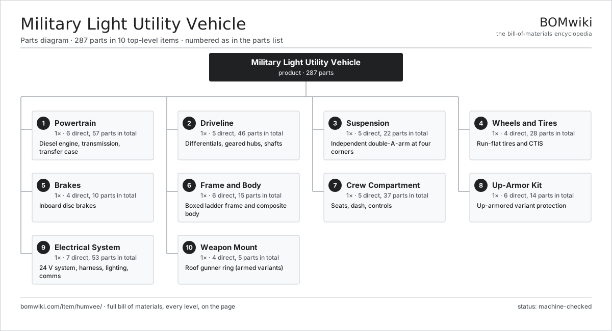
| # | Part | Qty | What it does |
|---|---|---|---|
| 1 | Powertrain 6 parts | 1× | Diesel engine, transmission, transfer case |
| 2 | Driveline 5 parts | 1× | Differentials, geared hubs, shafts |
| 3 | Suspension 5 parts | 1× | Independent double-A-arm at four corners |
| 4 | Wheels and Tires 4 parts | 1× | Run-flat tires and CTIS |
| 5 | Brakes 4 parts | 1× | Inboard disc brakes |
| 6 | Frame and Body 6 parts | 1× | Boxed ladder frame and composite body |
| 7 | Crew Compartment 5 parts | 1× | Seats, dash, controls |
| 8 | Up-Armor Kit 6 parts | 1× | Up-armored variant protection |
| 9 | Electrical System 7 parts | 1× | 24 V system, harness, lighting, comms |
| 10 | Weapon Mount 4 parts | 1× | Roof gunner ring (armed variants) |
3D model
No 3D model yet. Have a CAD file of this? Add a 3D model. STL renders right on this page; STEP, FreeCAD, and OpenSCAD sources are welcome too (openly licensed, like all 3D models on BOMwiki).
Build & assembly graph
expand / collapse · shared sub-assemblies converge · links to related products · est. labourTap an assembly to expand/collapse · tap a part to open it · use “Open page” for any node · drag to pan, scroll to zoom.
Bill of materials for Military Light Utility Vehicle
10 top-level lines · 111 rows shown · 287 parts total · indented to 3 levels| # | Item / sub-assembly | Part no. | Qty/assy | Ext. qty | Parts | Type |
|---|---|---|---|---|---|---|
| 1 | Powertrain 6 parts | humvee-powertrain | 1× | 1 | 57 | assembly |
| 1.1 | 6.5 L V8 Diesel Engine 9 parts | humvee-engine | 1× | 1 | 27 | assembly |
| 1.1.1 | Cylinder Block | humvee-cylinder-block | 1× | 1 | · | part |
| 1.1.2 | Cylinder Head | humvee-cylinder-head | 2× | 2 | · | part |
| 1.1.3 | Crankshaft | humvee-crankshaft | 1× | 1 | · | part |
| 1.1.4 | Piston | humvee-piston | 8× | 8 | · | part |
| 1.1.5 | Turbocharger | humvee-turbocharger | 1× | 1 | · | part |
| 1.1.6 | Injection Pump | humvee-injection-pump | 1× | 1 | · | part |
| 1.1.7 | Glow Plug | humvee-glow-plug | 8× | 8 | · | part |
| 1.1.8 | Oil Seal | oil-seal | 4× | 4 | · | part |
| 1.1.9 | Fastener Set | fastener-set | 1× | 1 | · | part |
| 1.2 | Automatic Transmission 5 parts | humvee-transmission | 1× | 1 | 15 | assembly |
| 1.2.1 | Torque Converter | humvee-torque-converter | 1× | 1 | · | part |
| 1.2.2 | Gearbox Housing | gearbox-housing | 1× | 1 | · | part |
| 1.2.3 | Helical Gear Pair | gear-pair | 4× | 4 | · | part |
| 1.2.4 | Ball Bearing | ball-bearing | 6× | 6 | · | part |
| 1.2.5 | Oil Seal | oil-seal | 3× | 3 | · | part |
| 1.3 | Transfer Case 5 parts | humvee-transfer-case | 1× | 1 | 12 | assembly |
| 1.3.1 | Gearbox Housing | gearbox-housing | 1× | 1 | · | part |
| 1.3.2 | Helical Gear Pair | gear-pair | 3× | 3 | · | part |
| 1.3.3 | Center Differential | humvee-center-diff | 1× | 1 | · | part |
| 1.3.4 | Ball Bearing | ball-bearing | 4× | 4 | · | part |
| 1.3.5 | Oil Seal | oil-seal | 3× | 3 | · | part |
| 1.4 | Exhaust System | humvee-exhaust | 1× | 1 | · | part |
| 1.5 | Radiator | radiator | 1× | 1 | · | part |
| 1.6 | Coolant Pump | coolant-pump | 1× | 1 | · | part |
| 2 | Driveline 5 parts | humvee-driveline | 1× | 1 | 46 | assembly |
| 2.1 | Front Differential 4 parts | humvee-front-diff | 1× | 1 | 8 | assembly |
| 2.1.1 | Helical Gear Pair | gear-pair | 1× | 1 | · | part |
| 2.1.2 | Differential Carrier | humvee-diff-carrier | 1× | 1 | · | part |
| 2.1.3 | Ball Bearing | ball-bearing | 4× | 4 | · | part |
| 2.1.4 | Oil Seal | oil-seal | 2× | 2 | · | part |
| 2.2 | Rear Differential 4 parts | humvee-rear-diff | 1× | 1 | 8 | assembly |
| 2.2.1 | Helical Gear Pair | gear-pair | 1× | 1 | · | part |
| 2.2.2 | Differential Carrier | humvee-diff-carrier | 1× | 1 | · | part |
| 2.2.3 | Ball Bearing | ball-bearing | 4× | 4 | · | part |
| 2.2.4 | Oil Seal | oil-seal | 2× | 2 | · | part |
| 2.3 | Geared Hub 4 parts | humvee-geared-hub | 4× | 4 | 6 | assembly |
| 2.3.1 | Helical Gear Pair | gear-pair | 1× | 4 | · | part |
| 2.3.2 | Hub Housing | humvee-hub-housing | 1× | 4 | · | part |
| 2.3.3 | Ball Bearing | ball-bearing | 2× | 8 | · | part |
| 2.3.4 | Oil Seal | oil-seal | 2× | 8 | · | part |
| 2.4 | Half-Shaft | humvee-half-shaft | 4× | 4 | · | part |
| 2.5 | Propeller Shaft | humvee-prop-shaft | 2× | 2 | · | part |
| 3 | Suspension 5 parts | humvee-suspension | 1× | 1 | 22 | assembly |
| 3.1 | Control Arm | humvee-control-arm | 8× | 8 | · | part |
| 3.2 | Coil Spring | coil-spring | 4× | 4 | · | part |
| 3.3 | Shock Absorber | humvee-shock-absorber | 4× | 4 | · | part |
| 3.4 | Stabilizer Bar | humvee-stabilizer-bar | 2× | 2 | · | part |
| 3.5 | Ball Bearing | ball-bearing | 4× | 4 | · | part |
| 4 | Wheels and Tires 4 parts | humvee-wheels-tires | 1× | 1 | 28 | assembly |
| 4.1 | Wheel Rim | humvee-wheel-rim | 4× | 4 | · | part |
| 4.2 | Tire | humvee-tire | 4× | 4 | · | part |
| 4.3 | Run-Flat Insert | humvee-runflat-insert | 4× | 4 | · | part |
| 4.4 | Central Tire Inflation System 4 parts | humvee-ctis | 1× | 1 | 16 | assembly |
| 4.4.1 | Air Compressor | humvee-air-compressor | 1× | 1 | · | part |
| 4.4.2 | Air Valve and Rotary Union | humvee-air-valve | 4× | 4 | · | part |
| 4.4.3 | Pressure Sensor | pressure-sensor | 4× | 4 | · | part |
| 4.4.4 | CTIS Controller 4 parts + deeper › | humvee-ctis-controller | 1× | 1 | 7 | assembly |
| 5 | Brakes 4 parts | humvee-brakes | 1× | 1 | 10 | assembly |
| 5.1 | Brake Disc | humvee-brake-disc | 4× | 4 | · | part |
| 5.2 | Brake Caliper | humvee-brake-caliper | 4× | 4 | · | part |
| 5.3 | Master Cylinder | humvee-master-cylinder | 1× | 1 | · | part |
| 5.4 | Brake Line Set | humvee-brake-line | 1× | 1 | · | part |
| 6 | Frame and Body 6 parts | humvee-frame-body | 1× | 1 | 15 | assembly |
| 6.1 | Ladder Frame | humvee-ladder-frame | 1× | 1 | · | part |
| 6.2 | Body Tub | humvee-body-tub | 1× | 1 | · | part |
| 6.3 | Sheet Metal Panel | sheet-panel | 6× | 6 | · | part |
| 6.4 | Bumper | humvee-bumper | 2× | 2 | · | part |
| 6.5 | Tow Hook | humvee-tow-hook | 4× | 4 | · | part |
| 6.6 | Fastener Set | fastener-set | 1× | 1 | · | part |
| 7 | Crew Compartment 5 parts | humvee-crew-compartment | 1× | 1 | 37 | assembly |
| 7.1 | Seat Assembly 5 parts | seat-assembly | 4× | 4 | 7 | assembly |
| 7.1.1 | Seat Frame | seat-frame | 1× | 4 | · | part |
| 7.1.2 | Seat Foam | seat-foam | 2× | 8 | · | part |
| 7.1.3 | Seat Cover | seat-cover | 1× | 4 | · | part |
| 7.1.4 | Seat Motor | seat-motor | 2× | 8 | · | part |
| 7.1.5 | Seat Heater Mat | seat-heater | 1× | 4 | · | part |
| 7.2 | Dashboard | humvee-dashboard | 1× | 1 | · | part |
| 7.3 | Steering Column and Gearbox 3 parts | humvee-steering-column | 1× | 1 | 4 | assembly |
| 7.3.1 | Steering Gearbox | humvee-steering-gearbox | 1× | 1 | · | part |
| 7.3.2 | Power Steering Pump | humvee-power-steering-pump | 1× | 1 | · | part |
| 7.3.3 | Tie Rod | humvee-tie-rod | 2× | 2 | · | part |
| 7.4 | HVAC Unit 3 parts | humvee-hvac | 1× | 1 | 3 | assembly |
| 7.4.1 | Heating Element | heating-element | 1× | 1 | · | part |
| 7.4.2 | Blower Fan | humvee-blower-fan | 1× | 1 | · | part |
| 7.4.3 | Heater Core | humvee-heater-core | 1× | 1 | · | part |
| 7.5 | Windshield | humvee-windshield | 1× | 1 | · | part |
| 8 | Up-Armor Kit 6 parts | humvee-armor-kit | 1× | 1 | 14 | assembly |
| 8.1 | Armored Door | humvee-armored-door | 4× | 4 | · | part |
| 8.2 | Armored Glass | humvee-armored-glass | 5× | 5 | · | part |
| 8.3 | Underbody Armor | humvee-underbody-armor | 1× | 1 | · | part |
| 8.4 | Side Armor Plate | humvee-side-armor | 2× | 2 | · | part |
| 8.5 | Roof Armor Panel | humvee-roof-armor | 1× | 1 | · | part |
| 8.6 | Fastener Set | fastener-set | 1× | 1 | · | part |
| 9 | Electrical System 7 parts | humvee-electrical | 1× | 1 | 53 | assembly |
| 9.1 | Alternator | humvee-alternator | 1× | 1 | · | part |
| 9.2 | 12 V Battery | lv-battery | 2× | 2 | · | part |
| 9.3 | Wire Bundle | wire-bundle | 1× | 1 | · | part |
| 9.4 | Light Unit | humvee-light-unit | 6× | 6 | · | part |
| 9.5 | Starter Motor 3 parts | humvee-starter | 1× | 1 | 23 | assembly |
| 9.5.1 | Stator Assembly 3 parts + deeper › | stator-assembly | 1× | 1 | 3 | assembly |
| 9.5.2 | Rotor Assembly 4 parts + deeper › | rotor-assembly | 1× | 1 | 19 | assembly |
| 9.5.3 | Helical Gear Pair | gear-pair | 1× | 1 | · | part |
| 9.6 | Connector | connector | 12× | 12 | · | part |
| 9.7 | Relay | relay | 8× | 8 | · | part |
| 10 | Weapon Mount 4 parts | humvee-weapon-mount | 1× | 1 | 5 | assembly |
| 10.1 | Turret Ring | humvee-turret-ring | 1× | 1 | · | part |
| 10.2 | Weapon Cradle | humvee-weapon-cradle | 1× | 1 | · | part |
| 10.3 | Gunner Shield | humvee-gun-shield | 1× | 1 | · | part |
| 10.4 | Ball Bearing | ball-bearing | 2× | 2 | · | part |
Related products
same domain, ranked by shared parts Amphibious Assault Vehicle
894 parts · shares 24 with this page
Amphibious Assault Vehicle
894 parts · shares 24 with this page
 Armored Recovery Vehicle
728 parts · shares 23 with this page
Armored Recovery Vehicle
728 parts · shares 23 with this page
 Self-Propelled Howitzer
848 parts · shares 23 with this page
Self-Propelled Howitzer
848 parts · shares 23 with this page
 Landing Craft
613 parts · shares 22 with this page
Landing Craft
613 parts · shares 22 with this page
 Patrol Boat
298 parts · shares 21 with this page
Patrol Boat
298 parts · shares 21 with this page
 Armored Personnel Carrier
221 parts · shares 10 with this page
Armored Personnel Carrier
221 parts · shares 10 with this page
Sourcing: possible vendors
Browse the supplier directory → Prices, MOQ, and lead times are algorithmic estimates, not quotes, and not claims about these companies. Company mappings are curated by keyword; est. price band $200–$100M. How estimates work| Vendor | HQ | Specialty | MOQ | Lead time |
|---|---|---|---|---|
| smithsdetection.com ↗ | London, GB | Security screening | made to order | 24–52 wks |
|
🇺🇸Leidos
leidos.com ↗
|
Reston, US | Security & screening | made to order | 24–52 wks |
|
🇺🇸Rapiscan
rapiscansystems.com ↗
|
Torrance, US | X-ray screening | made to order | 24–52 wks |
|
🇫🇷Thales
thalesgroup.com ↗
|
Paris, FR | Defense electronics | made to order | 24–52 wks |
| baesystems.com ↗ | London, GB | Defense | made to order | 24–52 wks |
893-word article