Pressure Relief Valve
ProductOverview
A pressure relief valve is the last line of defense against overpressure. It stays shut while a system runs normally and opens automatically only when pressure climbs to a preset limit, venting enough fluid to stop the pressure rising and then closing again once the system is safe. Unlike an operated valve it has no external power or signal, the process fluid acts directly on a disc, and a calibrated spring decides when that disc lifts.
The Body & Nozzle carries the inlet nozzle and the seat the disc closes against. The Disc & Holder sits on that seat, held down by the Spring Assembly. The Bonnet & Cap encloses the spring and the screw that compresses it, the Blowdown Ring tunes when the valve recloses, the Set-Pressure Adjustment locks and seals the setting, and the Test Gag lets the vessel be hydrotested without the valve lifting.
How it works
System pressure pushes up on the Disc over the nozzle bore while the Coil Spring pushes down through the Spindle. The two are balanced right up to the set pressure; the moment fluid force just exceeds spring force the disc cracks open. As soon as it lifts, fluid acts on the larger face of the Disc Holder and on the surface exposed by the Blowdown Ring, so the opening force jumps and the valve pops fully open rather than weeping. This snap action is what gives a relief valve its rated discharge capacity.
The valve must also reclose cleanly. The Blowdown Ring sets the reseating pressure, the blowdown, by controlling how much the escaping fluid keeps holding the disc up. Set too tight, the valve chatters; set too loose, it stays open well below set pressure and wastes product. Tuning it trades a clean pop against a clean reseat on the Nozzle Seat.
Set pressure is dialed in with the Adjusting Screw, then frozen with the Locknut and a lead Seal Wire so any tampering is visible. Because the valve is a certified safety device, that seal, the orifice size, and the spring range are all stamped and documented, and the Cap covers the adjustment so it cannot drift in service.
Pressure Relief Valve parts and their functions
9 top-level parts · 19 parts in total · full bill of materials below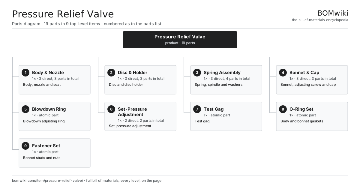
| # | Part | Qty | What it does |
|---|---|---|---|
| 1 | Body & Nozzle 3 parts | 1× | Body, nozzle and seat |
| 2 | Disc & Holder 3 parts | 1× | Disc and disc holder |
| 3 | Spring Assembly 3 parts | 1× | Spring, spindle and washers |
| 4 | Bonnet & Cap 3 parts | 1× | Bonnet, adjusting screw and cap |
| 5 | Blowdown Ring | 1× | Blowdown adjusting ring |
| 6 | Set-Pressure Adjustment 2 parts | 1× | Set-pressure adjustment |
| 7 | Test Gag | 1× | Test gag |
| 8 | O-Ring Set | 1× | Body and bonnet gaskets |
| 9 | Fastener Set | 1× | Bonnet studs and nuts |
3D model
No 3D model yet. Have a CAD file of this? Add a 3D model. STL renders right on this page; STEP, FreeCAD, and OpenSCAD sources are welcome too (openly licensed, like all 3D models on BOMwiki).
Build & assembly graph
expand / collapse · shared sub-assemblies converge · links to related products · est. labourTap an assembly to expand/collapse · tap a part to open it · use “Open page” for any node · drag to pan, scroll to zoom.
Bill of materials for Pressure Relief Valve
9 top-level lines · 23 rows shown · 19 parts total · indented to 3 levels| # | Item / sub-assembly | Part no. | Qty/assy | Ext. qty | Parts | Type |
|---|---|---|---|---|---|---|
| 1 | Body & Nozzle 3 parts | prv-body-assy | 1× | 1 | 3 | assembly |
| 1.1 | Valve Body | prv-body | 1× | 1 | · | part |
| 1.2 | Nozzle | prv-nozzle | 1× | 1 | · | part |
| 1.3 | Nozzle Seat | prv-seat | 1× | 1 | · | part |
| 2 | Disc & Holder 3 parts | prv-disc-holder-assy | 1× | 1 | 3 | assembly |
| 2.1 | Disc | prv-disc | 1× | 1 | · | part |
| 2.2 | Disc Holder | prv-disc-holder | 1× | 1 | · | part |
| 2.3 | Disc Guide | prv-guide | 1× | 1 | · | part |
| 3 | Spring Assembly 3 parts | prv-spring-assy | 1× | 1 | 4 | assembly |
| 3.1 | Coil Spring | coil-spring | 1× | 1 | · | part |
| 3.2 | Spindle | prv-spindle | 1× | 1 | · | part |
| 3.3 | Spring Washer | prv-spring-washer | 2× | 2 | · | part |
| 4 | Bonnet & Cap 3 parts | prv-bonnet-assy | 1× | 1 | 3 | assembly |
| 4.1 | Bonnet | prv-bonnet | 1× | 1 | · | part |
| 4.2 | Adjusting Screw | prv-adjusting-screw | 1× | 1 | · | part |
| 4.3 | Cap | prv-cap | 1× | 1 | · | part |
| 5 | Blowdown Ring | prv-blowdown-ring | 1× | 1 | · | part |
| 6 | Set-Pressure Adjustment 2 parts | prv-set-adjust | 1× | 1 | 2 | assembly |
| 6.1 | Locknut | prv-locknut | 1× | 1 | · | part |
| 6.2 | Seal Wire | prv-seal-wire | 1× | 1 | · | part |
| 7 | Test Gag | prv-test-gag | 1× | 1 | · | part |
| 8 | O-Ring Set | oring-set | 1× | 1 | · | part |
| 9 | Fastener Set | fastener-set | 1× | 1 | · | part |
Something wrong in this list? Report a problem with this BOM.
Used in 1 assembly
Related products
same domain, ranked by shared parts Control Valve
46 parts · shares 1 with this page
Directional Control Valve
32 parts · shares 1 with this page
 High-Pressure Plunger Pump
115 parts · shares 1 with this page
 Hydraulic Power Unit
91 parts · shares 1 with this page
Hydraulic Test Bench
77 parts · shares 1 with this page
Sourcing: possible vendors
Browse the supplier directory → Prices, MOQ, and lead times are algorithmic estimates, not quotes, and not claims about these companies. Company mappings are curated by keyword; est. price band $50–$50k. How estimates work| Vendor | HQ | Specialty | MOQ | Lead time |
|---|---|---|---|---|
|
🇩🇰Grundfos
grundfos.com ↗
|
Bjerringbro, DK | Pumps | 200 units | 6–12 wks |
|
🇺🇸Xylem
xylem.com ↗
|
Washington, US | Water technology | 200 units | 6–12 wks |
| flowserve.com ↗ | Irving, US | Pumps & valves | 200 units | 6–12 wks |
|
🇩🇪KSB
ksb.com ↗
|
Frankenthal, DE | Pumps & valves | 200 units | 6–12 wks |
| parker.com ↗ | Cleveland, US | Motion & fluid control | 200 units | 6–12 wks |
376-word article