Irrigation Pump Station
ProductOverview
An irrigation pump station lifts water from a low source, a canal, river, or reservoir, into a pressurised or elevated irrigation main that feeds field channels and sprinkler or drip networks. Where gravity cannot deliver the head a scheme needs, a lift station bridges the gap. A typical station uses several pumps in parallel so flow can be matched to seasonal demand and so a failed unit never stops irrigation. This station carries four Pump Set units, three running as duty pumps and one held as standby, drawing through a shared Intake Structure and discharging into a common Discharge Header.
The pumps are multi-stage vertical turbine machines hung in a wet pit. This layout suits the wide and variable water levels of canals, the bowls stay submerged even at low canal stage, so the pumps never lose suction. Each pump is driven from above by a vertical hollow-shaft motor, with the line shaft passing down through the column pipe to the bowls below.
How it works
Water enters the Wet Well through a Trash Rack and Bar Screen that hold back weed mats, branches, and floating trash. A motorised Mechanical Screen Rake combs debris off the screen so head loss stays low. Each pump draws from the well through a flared Suction Bell sized to feed the bowls without forming a vortex, which would draw air and break the pump's prime.
Inside each Vertical Turbine Pump, a stack of bronze impellers raises the water stage by stage up the riser column to the discharge head, then out into the header. The pumps run against a system head that combines the static lift from canal level to the main plus the friction loss in the column, header, and downstream pipe. The station designer plots this system head curve against the pump curves; the operating point sits where the two cross. As more duty pumps start, the combined pump curve shifts right and the operating point moves up the steeper part of the system curve, so each added pump yields less extra flow than the last.
Speed is set by a Variable Frequency Drive per motor. The drive soft-starts the motor, ramping voltage and frequency so the pump comes up to speed without the high inrush current and torque shock of across-the-line starting, which is hard on shafts, couplings, and the supply. In running, the PLC trims drive speed to hold a target header pressure or canal drawdown rate, so the station follows demand without throttling valves and wasting energy.
Subsystems
The Discharge Header collects all four pump branches. Each branch carries an Isolation Valve so one pump can be shut and serviced while the others run, and an Non-Return Check Valve that stops reverse flow when a pump stops. An Air Release Valve vents trapped air at high points, and an electromagnetic Flow Meter logs total delivery for water accounting.
The Motor Control Centre holds the four drives, the incoming breaker, busbars, and bypass contactors. The Control System reads wet-well level, header pressure, and pump vibration, sequences the duty-standby rotation so running hours even out across the pumps, and trips a pump on low level, high vibration, or motor overload. A Priming System is fitted for any horizontal centrifugal pumps in the scheme; a liquid-ring Vacuum Pump evacuates the casing so the pump fills before start.
Pump and motor
Each Drive Motor is a vertical hollow-shaft induction machine. The pump line shaft passes up through the hollow rotor and is clamped at the top by an adjustable Shaft Coupling that also sets impeller lift off the bowl seats. A Thrust Bearing in the motor carries the full down-thrust of the impellers and the shaft, the largest mechanical load in the machine. The Mechanical Seal at the discharge head keeps pumped water from tracking up the shaft. Renewable Wear Ring components control internal leakage between impeller and bowl; replacing them at overhaul restores efficiency without re-machining the castings.
Surge and control
The most severe load on the pipework is water hammer. When several duty pumps trip together, on a power failure for example, flow in the long discharge main decelerates fast, and the momentum of the moving column drives a pressure surge that can burst pipe or collapse it on the rebound. The Surge Protection limits this. A Surge Vessel with a compressed air cushion feeds water into the main as the pumps coast down, holding pressure up and cushioning the wave; a small Air Compressor tops up the cushion as air slowly dissolves into the water. A Surge Relief Valve dumps water to drain if pressure still climbs past the set point. The fast-closing nozzle Non-Return Check Valve on each branch shuts before reverse flow builds, cutting the slam at the pump.
Materials
Bowls and the discharge head are cast iron for cost and castability; impellers are bronze for cavitation and corrosion resistance in raw water carrying silt. Line shafts are stainless. The header and column pipe are coated carbon steel. Seals use carbon against silicon carbide faces with elastomer secondary seals chosen for the water chemistry. In canal water with high sand content, hard-coated wear rings and bowls extend overhaul intervals.
Common failures
Cavitation is the most common problem when canal level falls and the available suction head drops below what the pump needs; it erodes impellers and bowls and shows up as rising vibration that the Vibration Sensor catches. Silt wears impellers, wear rings, and shaft bearings, so flow and head fall off over a season. Line-shaft bearing wear lets the shaft whirl and rub. Air valves stick on debris and let air pockets block flow. On the electrical side, drive faults trip pumps; the bypass contactor lets a motor run across the line until the drive is repaired. Trash screen blinding starves the pumps if the rake fails, so screen differential level is alarmed.
Irrigation Pump Station parts and their functions
9 top-level parts · 1,881 parts in total · full bill of materials below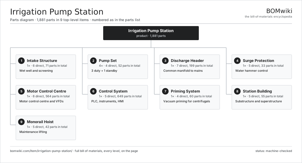
| # | Part | Qty | What it does |
|---|---|---|---|
| 1 | Intake Structure 6 parts | 1× | Wet well and screening |
| 2 | Pump Set 4 parts | 4× | 3 duty + 1 standby |
| 3 | Discharge Header 7 parts | 1× | Common manifold to mains |
| 4 | Surge Protection 5 parts | 1× | Water hammer control |
| 5 | Motor Control Centre 6 parts | 1× | Motor control centre and VFDs |
| 6 | Control System 5 parts | 1× | PLC, instruments, HMI |
| 7 | Priming System 4 parts | 1× | Vacuum priming for centrifugals |
| 8 | Station Building 5 parts | 1× | Substructure and superstructure |
| 9 | Monorail Hoist 5 parts | 1× | Maintenance lifting |
3D model
No 3D model yet. Have a CAD file of this? Add a 3D model. STL renders right on this page; STEP, FreeCAD, and OpenSCAD sources are welcome too (openly licensed, like all 3D models on BOMwiki).
Build & assembly graph
expand / collapse · shared sub-assemblies converge · links to related products · est. labourTap an assembly to expand/collapse · tap a part to open it · use “Open page” for any node · drag to pan, scroll to zoom.
Bill of materials for Irrigation Pump Station
9 top-level lines · 153 rows shown · 1,881 parts total · indented to 3 levels| # | Item / sub-assembly | Part no. | Qty/assy | Ext. qty | Parts | Type |
|---|---|---|---|---|---|---|
| 1 | Intake Structure 6 parts | irrigation-pump-station-intake-structure | 1× | 1 | 71 | assembly |
| 1.1 | Wet Well | irrigation-pump-station-wet-well | 1× | 1 | · | part |
| 1.2 | Bar Screen | irrigation-pump-station-bar-screen | 1× | 1 | · | part |
| 1.3 | Mechanical Screen Rake 4 parts | irrigation-pump-station-screen-rake | 1× | 1 | 34 | assembly |
| 1.3.1 | Rake Drive Unit 6 parts + deeper › | irrigation-pump-station-rake-drive | 1× | 1 | 28 | assembly |
| 1.3.2 | Rake Tine Bar | irrigation-pump-station-rake-tines | 1× | 1 | · | part |
| 1.3.3 | Ball Bearing | ball-bearing | 4× | 4 | · | part |
| 1.3.4 | Fastener Set | fastener-set | 1× | 1 | · | part |
| 1.4 | Inlet Stop Gate 4 parts | irrigation-pump-station-inlet-stop-gate | 1× | 1 | 30 | assembly |
| 1.4.1 | Gate Leaf | irrigation-pump-station-gate-leaf | 1× | 1 | · | part |
| 1.4.2 | Gate Stem | irrigation-pump-station-gate-stem | 1× | 1 | · | part |
| 1.4.3 | Gate Actuator 5 parts + deeper › | irrigation-pump-station-gate-actuator | 1× | 1 | 26 | assembly |
| 1.4.4 | O-Ring Set | oring-set | 2× | 2 | · | part |
| 1.5 | Trash Rack | irrigation-pump-station-trash-rack | 1× | 1 | · | part |
| 1.6 | Suction Bell | irrigation-pump-station-suction-bell | 4× | 4 | · | part |
| 2 | Pump Set 4 parts | irrigation-pump-station-pump-set | 4× | 4 | 52 | assembly |
| 2.1 | Vertical Turbine Pump 8 parts | irrigation-pump-station-pump | 1× | 4 | 18 | assembly |
| 2.1.1 | Pump Bowl Casing | irrigation-pump-station-pump-casing | 1× | 4 | · | part |
| 2.1.2 | Impeller | irrigation-pump-station-impeller | 3× | 12 | · | part |
| 2.1.3 | Pump Line Shaft | irrigation-pump-station-pump-shaft | 1× | 4 | · | part |
| 2.1.4 | Wear Ring | irrigation-pump-station-wear-ring | 3× | 12 | · | part |
| 2.1.5 | Mechanical Seal 3 parts + deeper › | irrigation-pump-station-mechanical-seal | 1× | 4 | 4 | assembly |
| 2.1.6 | Column Pipe | irrigation-pump-station-column-pipe | 1× | 4 | · | part |
| 2.1.7 | Line-Shaft Bearing | irrigation-pump-station-shaft-bearing | 4× | 16 | · | part |
| 2.1.8 | Suction Strainer | irrigation-pump-station-suction-strainer | 1× | 4 | · | part |
| 2.2 | Drive Motor 7 parts | irrigation-pump-station-motor | 1× | 4 | 32 | assembly |
| 2.2.1 | Stator Assembly 3 parts + deeper › | stator-assembly | 1× | 4 | 3 | assembly |
| 2.2.2 | Rotor Assembly 4 parts + deeper › | rotor-assembly | 1× | 4 | 19 | assembly |
| 2.2.3 | Motor Frame | irrigation-pump-station-motor-frame | 1× | 4 | · | part |
| 2.2.4 | Ball Bearing | ball-bearing | 2× | 8 | · | part |
| 2.2.5 | Thrust Bearing | irrigation-pump-station-thrust-bearing | 1× | 4 | · | part |
| 2.2.6 | Cooling Fan | irrigation-pump-station-cooling-fan | 1× | 4 | · | part |
| 2.2.7 | Terminal Box 3 parts + deeper › | irrigation-pump-station-terminal-box | 1× | 4 | 5 | assembly |
| 2.3 | Discharge Head and Base | irrigation-pump-station-pump-baseplate | 1× | 4 | · | part |
| 2.4 | Shaft Coupling | irrigation-pump-station-coupling | 1× | 4 | · | part |
| 3 | Discharge Header 7 parts | irrigation-pump-station-discharge-header | 1× | 1 | 199 | assembly |
| 3.1 | Header Pipe Spool | irrigation-pump-station-header-pipe | 1× | 1 | · | part |
| 3.2 | Isolation Valve 4 parts | irrigation-pump-station-isolation-valve | 4× | 4 | 31 | assembly |
| 3.2.1 | Valve Body | irrigation-pump-station-valve-body | 1× | 4 | · | part |
| 3.2.2 | Valve Disc | irrigation-pump-station-valve-disc | 1× | 4 | · | part |
| 3.2.3 | Valve Actuator 6 parts + deeper › | irrigation-pump-station-valve-actuator | 1× | 4 | 27 | assembly |
| 3.2.4 | O-Ring Set | oring-set | 2× | 8 | · | part |
| 3.3 | Non-Return Check Valve 4 parts | irrigation-pump-station-check-valve | 4× | 4 | 4 | assembly |
| 3.3.1 | Check Valve Body | irrigation-pump-station-check-body | 1× | 4 | · | part |
| 3.3.2 | Check Disc | irrigation-pump-station-check-disc | 1× | 4 | · | part |
| 3.3.3 | Coil Spring | coil-spring | 1× | 4 | · | part |
| 3.3.4 | O-Ring Set | oring-set | 1× | 4 | · | part |
| 3.4 | Air Release Valve 3 parts | irrigation-pump-station-air-release-valve | 2× | 2 | 3 | assembly |
| 3.4.1 | Air Valve Float | irrigation-pump-station-arv-float | 1× | 2 | · | part |
| 3.4.2 | Valve Body | irrigation-pump-station-valve-body | 1× | 2 | · | part |
| 3.4.3 | O-Ring Set | oring-set | 1× | 2 | · | part |
| 3.5 | Flow Meter 5 parts | irrigation-pump-station-flow-meter | 1× | 1 | 44 | assembly |
| 3.5.1 | Flow Sensor Tube | irrigation-pump-station-flow-sensor | 1× | 1 | · | part |
| 3.5.2 | Bare PCB | pcb-bare | 1× | 1 | · | part |
| 3.5.3 | Microcontroller | mcu | 1× | 1 | · | part |
| 3.5.4 | SMD Passive (R/C/L) | smd-passives | 40× | 40 | · | part |
| 3.5.5 | LCD Panel | lcd-panel | 1× | 1 | · | part |
| 3.6 | Expansion Joint | irrigation-pump-station-expansion-joint | 2× | 2 | · | part |
| 3.7 | Pipe Support | irrigation-pump-station-pipe-support | 6× | 6 | · | part |
| 4 | Surge Protection 5 parts | irrigation-pump-station-surge-protection | 1× | 1 | 33 | assembly |
| 4.1 | Surge Vessel | irrigation-pump-station-surge-vessel | 1× | 1 | · | part |
| 4.2 | Air Compressor 5 parts | irrigation-pump-station-air-compressor | 1× | 1 | 27 | assembly |
| 4.2.1 | Stator Assembly 3 parts + deeper › | stator-assembly | 1× | 1 | 3 | assembly |
| 4.2.2 | Rotor Assembly 4 parts + deeper › | rotor-assembly | 1× | 1 | 19 | assembly |
| 4.2.3 | Compressor Head | irrigation-pump-station-compressor-head | 1× | 1 | · | part |
| 4.2.4 | Ball Bearing | ball-bearing | 2× | 2 | · | part |
| 4.2.5 | O-Ring Set | oring-set | 2× | 2 | · | part |
| 4.3 | Surge Relief Valve 3 parts | irrigation-pump-station-surge-relief-valve | 1× | 1 | 3 | assembly |
| 4.3.1 | Valve Body | irrigation-pump-station-valve-body | 1× | 1 | · | part |
| 4.3.2 | Coil Spring | coil-spring | 1× | 1 | · | part |
| 4.3.3 | O-Ring Set | oring-set | 1× | 1 | · | part |
| 4.4 | Level Gauge | irrigation-pump-station-level-gauge | 1× | 1 | · | part |
| 4.5 | Pressure Sensor | pressure-sensor | 1× | 1 | · | part |
| 5 | Motor Control Centre 6 parts | irrigation-pump-station-mcc | 1× | 1 | 564 | assembly |
| 5.1 | Variable Frequency Drive 5 parts | irrigation-pump-station-vfd | 4× | 4 | 129 | assembly |
| 5.1.1 | VFD Power Module | irrigation-pump-station-vfd-power-module | 1× | 4 | · | part |
| 5.1.2 | VFD Control Board 4 parts + deeper › | irrigation-pump-station-vfd-control-board | 1× | 4 | 124 | assembly |
| 5.1.3 | DC Link Capacitor Bank | irrigation-pump-station-dc-link | 1× | 4 | · | part |
| 5.1.4 | Line Reactor | irrigation-pump-station-line-reactor | 1× | 4 | · | part |
| 5.1.5 | VFD Cooling Fan | irrigation-pump-station-vfd-cooling-fan | 2× | 8 | · | part |
| 5.2 | MCC Cabinet | irrigation-pump-station-mcc-cabinet | 1× | 1 | · | part |
| 5.3 | Busbar System 3 parts | irrigation-pump-station-busbar-system | 1× | 1 | 10 | assembly |
| 5.3.1 | Copper Busbar | irrigation-pump-station-copper-busbar | 3× | 3 | · | part |
| 5.3.2 | Busbar Insulator | irrigation-pump-station-busbar-insulator | 6× | 6 | · | part |
| 5.3.3 | Fastener Set | fastener-set | 1× | 1 | · | part |
| 5.4 | Main Circuit Breaker | irrigation-pump-station-main-breaker | 1× | 1 | · | part |
| 5.5 | Bypass Contactor | irrigation-pump-station-contactor | 4× | 4 | · | part |
| 5.6 | Control Power Supply 3 parts | irrigation-pump-station-power-supply | 1× | 1 | 32 | assembly |
| 5.6.1 | Power Supply | power-supply | 1× | 1 | · | part |
| 5.6.2 | Bare PCB | pcb-bare | 1× | 1 | · | part |
| 5.6.3 | SMD Passive (R/C/L) | smd-passives | 30× | 30 | · | part |
| 6 | Control System 5 parts | irrigation-pump-station-control-system | 1× | 1 | 649 | assembly |
| 6.1 | PLC Panel 5 parts | irrigation-pump-station-plc-panel | 1× | 1 | 459 | assembly |
| 6.1.1 | PLC CPU Module 3 parts + deeper › | irrigation-pump-station-plc-cpu | 1× | 1 | 153 | assembly |
| 6.1.2 | I/O Module 4 parts + deeper › | irrigation-pump-station-io-module | 4× | 4 | 73 | assembly |
| 6.1.3 | Power Supply | power-supply | 1× | 1 | · | part |
| 6.1.4 | Relay | relay | 12× | 12 | · | part |
| 6.1.5 | Bare PCB | pcb-bare | 1× | 1 | · | part |
| 6.2 | Level Transmitter 4 parts | irrigation-pump-station-level-transmitter | 2× | 2 | 33 | assembly |
| 6.2.1 | Pressure Sensor | pressure-sensor | 1× | 2 | · | part |
| 6.2.2 | Bare PCB | pcb-bare | 1× | 2 | · | part |
| 6.2.3 | Microcontroller | mcu | 1× | 2 | · | part |
| 6.2.4 | SMD Passive (R/C/L) | smd-passives | 30× | 60 | · | part |
| 6.3 | Pressure Transmitter 4 parts | irrigation-pump-station-pressure-transmitter | 2× | 2 | 33 | assembly |
| 6.3.1 | Pressure Sensor | pressure-sensor | 1× | 2 | · | part |
| 6.3.2 | Bare PCB | pcb-bare | 1× | 2 | · | part |
| 6.3.3 | Microcontroller | mcu | 1× | 2 | · | part |
| 6.3.4 | SMD Passive (R/C/L) | smd-passives | 30× | 60 | · | part |
| 6.4 | HMI Panel 5 parts | irrigation-pump-station-hmi | 1× | 1 | 54 | assembly |
| 6.4.1 | LCD Panel | lcd-panel | 1× | 1 | · | part |
| 6.4.2 | Bare PCB | pcb-bare | 1× | 1 | · | part |
| 6.4.3 | Microcontroller | mcu | 1× | 1 | · | part |
| 6.4.4 | Power Supply | power-supply | 1× | 1 | · | part |
| 6.4.5 | SMD Passive (R/C/L) | smd-passives | 50× | 50 | · | part |
| 6.5 | Vibration Sensor | irrigation-pump-station-vibration-sensor | 4× | 4 | · | part |
| 7 | Priming System 4 parts | irrigation-pump-station-priming-system | 1× | 1 | 60 | assembly |
| 7.1 | Vacuum Pump 5 parts | irrigation-pump-station-vacuum-pump | 2× | 2 | 27 | assembly |
| 7.1.1 | Stator Assembly 3 parts + deeper › | stator-assembly | 1× | 2 | 3 | assembly |
| 7.1.2 | Rotor Assembly 4 parts + deeper › | rotor-assembly | 1× | 2 | 19 | assembly |
| 7.1.3 | Vacuum Pump Rotor | irrigation-pump-station-vacuum-rotor | 1× | 2 | · | part |
| 7.1.4 | Ball Bearing | ball-bearing | 2× | 4 | · | part |
| 7.1.5 | Oil Seal | oil-seal | 2× | 4 | · | part |
| 7.2 | Priming Tank | irrigation-pump-station-priming-tank | 1× | 1 | · | part |
| 7.3 | Priming Valve | irrigation-pump-station-priming-valve | 4× | 4 | · | part |
| 7.4 | Pressure Sensor | pressure-sensor | 1× | 1 | · | part |
| 8 | Station Building 5 parts | irrigation-pump-station-station-building | 1× | 1 | 55 | assembly |
| 8.1 | Foundation Block | irrigation-pump-station-foundation | 1× | 1 | · | part |
| 8.2 | Superstructure | irrigation-pump-station-superstructure | 1× | 1 | · | part |
| 8.3 | Access Door | irrigation-pump-station-access-doors | 2× | 2 | · | part |
| 8.4 | Ventilation Fan 4 parts | irrigation-pump-station-ventilation-fan | 2× | 2 | 25 | assembly |
| 8.4.1 | Stator Assembly 3 parts + deeper › | stator-assembly | 1× | 2 | 3 | assembly |
| 8.4.2 | Rotor Assembly 4 parts + deeper › | rotor-assembly | 1× | 2 | 19 | assembly |
| 8.4.3 | Ball Bearing | ball-bearing | 2× | 4 | · | part |
| 8.4.4 | Sheet Metal Panel | sheet-panel | 1× | 2 | · | part |
| 8.5 | Cable Trench | irrigation-pump-station-cable-trench | 1× | 1 | · | part |
| 9 | Monorail Hoist 5 parts | irrigation-pump-station-monorail-hoist | 1× | 1 | 42 | assembly |
| 9.1 | Monorail Beam | irrigation-pump-station-monorail-beam | 1× | 1 | · | part |
| 9.2 | Hoist Trolley 3 parts | irrigation-pump-station-hoist-trolley | 1× | 1 | 9 | assembly |
| 9.2.1 | Ball Bearing | ball-bearing | 4× | 4 | · | part |
| 9.2.2 | Trolley Wheel | irrigation-pump-station-trolley-wheel | 4× | 4 | · | part |
| 9.2.3 | Fastener Set | fastener-set | 1× | 1 | · | part |
| 9.3 | Hoist Motor 6 parts | irrigation-pump-station-hoist-motor | 1× | 1 | 27 | assembly |
| 9.3.1 | Stator Assembly 3 parts + deeper › | stator-assembly | 1× | 1 | 3 | assembly |
| 9.3.2 | Rotor Assembly 4 parts + deeper › | rotor-assembly | 1× | 1 | 19 | assembly |
| 9.3.3 | Helical Gear Pair | gear-pair | 1× | 1 | · | part |
| 9.3.4 | Gearbox Housing | gearbox-housing | 1× | 1 | · | part |
| 9.3.5 | Ball Bearing | ball-bearing | 2× | 2 | · | part |
| 9.3.6 | Oil Seal | oil-seal | 1× | 1 | · | part |
| 9.4 | Load Chain and Hook | irrigation-pump-station-load-chain | 1× | 1 | · | part |
| 9.5 | Pendant Control 3 parts | irrigation-pump-station-pendant | 1× | 1 | 4 | assembly |
| 9.5.1 | Bare PCB | pcb-bare | 1× | 1 | · | part |
| 9.5.2 | Connector | connector | 2× | 2 | · | part |
| 9.5.3 | Wire Bundle | wire-bundle | 1× | 1 | · | part |
Related products
same domain, ranked by shared parts Sluice Gate
123 parts · shares 10 with this page
Sluice Gate
123 parts · shares 10 with this page
 Radial Spillway Gate
264 parts · shares 10 with this page
Radial Spillway Gate
264 parts · shares 10 with this page
 Centrifugal Compressor
338 parts · shares 8 with this page
Centrifugal Compressor
338 parts · shares 8 with this page
 Hydraulic Cylinder
17 parts · shares 3 with this page
Hydraulic Cylinder
17 parts · shares 3 with this page
 Control Valve
46 parts · shares 7 with this page
Control Valve
46 parts · shares 7 with this page
 Ball Valve
61 parts · shares 7 with this page
Ball Valve
61 parts · shares 7 with this page
Sourcing: possible vendors
Browse the supplier directory → Prices, MOQ, and lead times are algorithmic estimates, not quotes, and not claims about these companies. Company mappings are curated by keyword; est. price band $50–$50k. How estimates work| Vendor | HQ | Specialty | MOQ | Lead time |
|---|---|---|---|---|
|
🇩🇰Grundfos
grundfos.com ↗
|
Bjerringbro, DK | Pumps | 200 units | 6–12 wks |
|
🇺🇸Xylem
xylem.com ↗
|
Washington, US | Water technology | 200 units | 6–12 wks |
| flowserve.com ↗ | Irving, US | Pumps & valves | 200 units | 6–12 wks |
|
🇩🇪KSB
ksb.com ↗
|
Frankenthal, DE | Pumps & valves | 200 units | 6–12 wks |
| parker.com ↗ | Cleveland, US | Motion & fluid control | 200 units | 6–12 wks |
1,071-word article