Gear Pump
ProductOverview
An external gear pump is a positive-displacement pump in which two meshing gears trap fluid between their teeth and the casing wall and carry it from suction to discharge. Because each revolution displaces a fixed volume, flow is steady and nearly independent of discharge pressure, which suits the pump to metering, fuel and lube transfer, and pumping viscous oils. The tight running clearances make it most efficient on clean, lubricating fluids. This unit is close-coupled to an electric motor through a flexible coupling.
Construction
Fluid is contained by the Pump Casing: a figure-eight cast-iron body bored for the two gears, closed by front and rear end covers carrying the shaft bushings, with pressure-balanced wear plates sealing the gear faces. The pumping element is the Gear Set, a drive gear and a free idler gear running on hardened shafts in sintered-bronze journal bushings. As the gears unmesh on the suction side they create the void that draws fluid in; the teeth carry it around the casing wall and squeeze it out as they remesh on the discharge side.
Where the drive shaft exits the casing it is sealed by the Shaft Seal, a rotary lip seal running on a replaceable hardened sleeve. To protect the pump and piping against overpressure or a blocked line, an integral Relief Valve cracks open above its setpoint and recirculates flow internally. Torque comes from the Electric Motor, a TEFC induction motor, joined to the pump by a flexible Flexible Coupling that tolerates minor shaft misalignment. The assembly is footed to a baseplate on a Mounting Foot and held together with a matched Fastener Set.
Gear Pump parts and their functions
8 top-level parts · 57 parts in total · full bill of materials below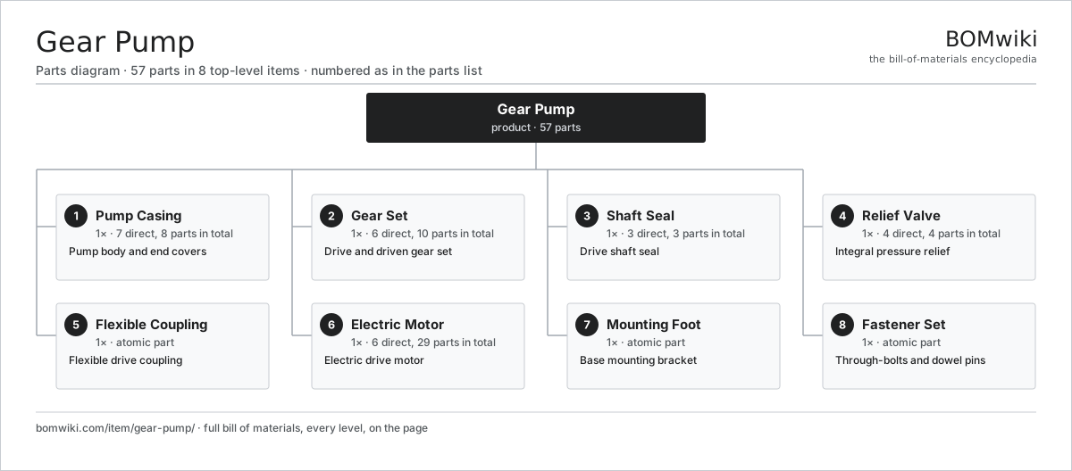
| # | Part | Qty | What it does |
|---|---|---|---|
| 1 | Pump Casing 7 parts | 1× | Pump body and end covers |
| 2 | Gear Set 6 parts | 1× | Drive and driven gear set |
| 3 | Shaft Seal 3 parts | 1× | Drive shaft seal |
| 4 | Relief Valve 4 parts | 1× | Integral pressure relief |
| 5 | Flexible Coupling | 1× | Flexible drive coupling |
| 6 | Electric Motor 6 parts | 1× | Electric drive motor |
| 7 | Mounting Foot | 1× | Base mounting bracket |
| 8 | Fastener Set | 1× | Through-bolts and dowel pins |
3D model
No 3D model yet. Have a CAD file of this? Add a 3D model. STL renders right on this page; STEP, FreeCAD, and OpenSCAD sources are welcome too (openly licensed, like all 3D models on BOMwiki).
Build & assembly graph
expand / collapse · shared sub-assemblies converge · links to related products · est. labourTap an assembly to expand/collapse · tap a part to open it · use “Open page” for any node · drag to pan, scroll to zoom.
Bill of materials for Gear Pump
8 top-level lines · 44 rows shown · 57 parts total · indented to 3 levels| # | Item / sub-assembly | Part no. | Qty/assy | Ext. qty | Parts | Type |
|---|---|---|---|---|---|---|
| 1 | Pump Casing 7 parts | gear-pump-casing | 1× | 1 | 8 | assembly |
| 1.1 | Pump Body | gear-pump-body | 1× | 1 | · | part |
| 1.2 | Front End Cover | gear-pump-front-cover | 1× | 1 | · | part |
| 1.3 | Rear End Cover | gear-pump-rear-cover | 1× | 1 | · | part |
| 1.4 | Wear Plate | gear-pump-wear-plate | 2× | 2 | · | part |
| 1.5 | Inlet Flange | gear-pump-inlet-flange | 1× | 1 | · | part |
| 1.6 | Outlet Flange | gear-pump-outlet-flange | 1× | 1 | · | part |
| 1.7 | O-Ring Set | oring-set | 1× | 1 | · | part |
| 2 | Gear Set 6 parts | gear-pump-gear-set | 1× | 1 | 10 | assembly |
| 2.1 | Helical Gear Pair | gear-pair | 1× | 1 | · | part |
| 2.2 | Drive Shaft | gear-pump-drive-shaft | 1× | 1 | · | part |
| 2.3 | Idler Shaft | gear-pump-idler-shaft | 1× | 1 | · | part |
| 2.4 | Journal Bushing | gear-pump-bushing | 4× | 4 | · | part |
| 2.5 | Ball Bearing | ball-bearing | 2× | 2 | · | part |
| 2.6 | Drive Gear Key | gear-pump-shaft-key | 1× | 1 | · | part |
| 3 | Shaft Seal 3 parts | gear-pump-shaft-seal | 1× | 1 | 3 | assembly |
| 3.1 | Oil Seal | oil-seal | 1× | 1 | · | part |
| 3.2 | Seal Sleeve | gear-pump-seal-sleeve | 1× | 1 | · | part |
| 3.3 | O-Ring Set | oring-set | 1× | 1 | · | part |
| 4 | Relief Valve 4 parts | gear-pump-relief-valve | 1× | 1 | 4 | assembly |
| 4.1 | Valve Poppet | gear-pump-valve-poppet | 1× | 1 | · | part |
| 4.2 | Valve Spring | gear-pump-valve-spring | 1× | 1 | · | part |
| 4.3 | Adjuster Screw | gear-pump-valve-adjuster | 1× | 1 | · | part |
| 4.4 | O-Ring Set | oring-set | 1× | 1 | · | part |
| 5 | Flexible Coupling | gear-pump-coupling | 1× | 1 | · | part |
| 6 | Electric Motor 6 parts | gear-pump-motor | 1× | 1 | 29 | assembly |
| 6.1 | Stator Assembly 3 parts | stator-assembly | 1× | 1 | 3 | assembly |
| 6.1.1 | Stator Core (laminations) | stator-core | 1× | 1 | · | part |
| 6.1.2 | Copper Winding | copper-winding | 1× | 1 | · | part |
| 6.1.3 | Slot Insulation | stator-insulation | 1× | 1 | · | part |
| 6.2 | Rotor Assembly 4 parts | rotor-assembly | 1× | 1 | 19 | assembly |
| 6.2.1 | Rotor Shaft | rotor-shaft | 1× | 1 | · | part |
| 6.2.2 | Rotor Core | rotor-core | 1× | 1 | · | part |
| 6.2.3 | Neodymium Magnet | neodymium-magnet | 16× | 16 | · | part |
| 6.2.4 | Ball Bearing | ball-bearing | 1× | 1 | · | part |
| 6.3 | Motor Housing | motor-housing | 1× | 1 | · | part |
| 6.4 | Ball Bearing | ball-bearing | 2× | 2 | · | part |
| 6.5 | Terminal Box 3 parts | gear-pump-terminal-box | 1× | 1 | 3 | assembly |
| 6.5.1 | Terminal Block | gear-pump-terminal-block | 1× | 1 | · | part |
| 6.5.2 | Wire Bundle | wire-bundle | 1× | 1 | · | part |
| 6.5.3 | Connector | connector | 1× | 1 | · | part |
| 6.6 | Cooling Fan | gear-pump-cooling-fan | 1× | 1 | · | part |
| 7 | Mounting Foot | gear-pump-mounting-foot | 1× | 1 | · | part |
| 8 | Fastener Set | fastener-set | 1× | 1 | · | part |
Something wrong in this list? Report a problem with this BOM.
Related products
same domain, ranked by shared parts Peristaltic Pump
59 parts · shares 5 with this page
 Irrigation Pump Station
1,881 parts · shares 4 with this page
 Ball Valve
61 parts · shares 4 with this page
 Air Compressor
97 parts · shares 4 with this page
 Centrifugal Pump
66 parts · shares 4 with this page
 Hydraulic Power Unit
91 parts · shares 4 with this page
Sourcing: possible vendors
Browse the supplier directory → Prices, MOQ, and lead times are algorithmic estimates, not quotes, and not claims about these companies. Company mappings are curated by keyword; est. price band $50–$50k. How estimates work| Vendor | HQ | Specialty | MOQ | Lead time |
|---|---|---|---|---|
|
🇩🇰Grundfos
grundfos.com ↗
|
Bjerringbro, DK | Pumps | 200 units | 6–12 wks |
|
🇺🇸Xylem
xylem.com ↗
|
Washington, US | Water technology | 200 units | 6–12 wks |
| flowserve.com ↗ | Irving, US | Pumps & valves | 200 units | 6–12 wks |
|
🇩🇪KSB
ksb.com ↗
|
Frankenthal, DE | Pumps & valves | 200 units | 6–12 wks |
| parker.com ↗ | Cleveland, US | Motion & fluid control | 200 units | 6–12 wks |
287-word article