Submersible Pump
ProductOverview
A borehole submersible pump is installed at depth in a well and pushes water up to the surface, rather than drawing it up by suction from above. Both the motor and the pump run fully submerged: the water-filled motor sits at the bottom and a stacked multistage hydraulic end above it lifts the water through many small pumping stages in series. Because lift is generated by pressure from below, a submersible avoids the suction-lift limit that caps surface pumps, which is what makes deep wells practical.
How it works
Drive comes from the Submersible Motor, a water-filled induction motor whose deionized fill fluid cools and lubricates the bearings while an equalizing diaphragm balances internal pressure against the well. A tilting-pad thrust bearing carries the downthrust of the whole impeller stack. Power reaches it through the Submersible Cable, a flat submersible cable spliced to the potted motor leads, and torque passes to the pump through the splined Motor Coupling.
The Hydraulic End does the lifting. It is a stack of eight identical stages, each an impeller spinning inside a fixed diffuser that converts velocity into pressure and feeds the next stage, so head builds cumulatively up the stack. Water enters through an intake strainer at the suction interconnector and leaves through the discharge head, where an integral check valve prevents backflow and water hammer. A Flow Shroud sleeve forces well water past the motor for cooling. At the surface a Control Box provides motor starting, run capacitance and overload protection, while a Pressure Switch cycles the pump on well demand. Inter-section joints are sealed by an O-Ring Set.
Submersible Pump parts and their functions
9 top-level parts · 84 parts in total · full bill of materials below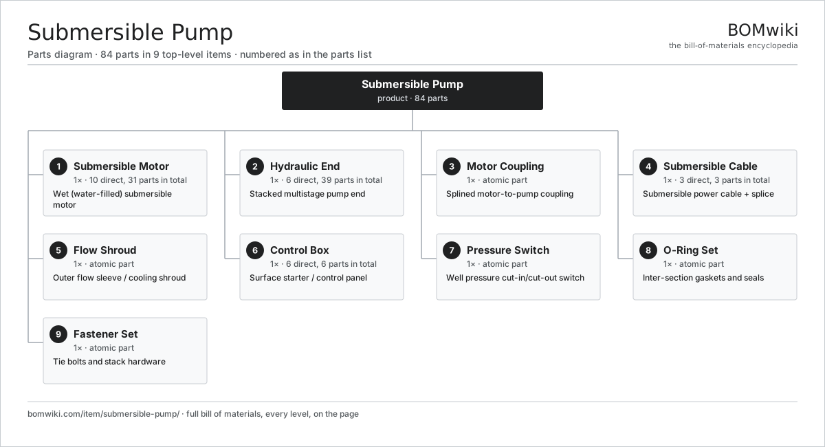
| # | Part | Qty | What it does |
|---|---|---|---|
| 1 | Submersible Motor 10 parts | 1× | Wet (water-filled) submersible motor |
| 2 | Hydraulic End 6 parts | 1× | Stacked multistage pump end |
| 3 | Motor Coupling | 1× | Splined motor-to-pump coupling |
| 4 | Submersible Cable 3 parts | 1× | Submersible power cable + splice |
| 5 | Flow Shroud | 1× | Outer flow sleeve / cooling shroud |
| 6 | Control Box 6 parts | 1× | Surface starter / control panel |
| 7 | Pressure Switch | 1× | Well pressure cut-in/cut-out switch |
| 8 | O-Ring Set | 1× | Inter-section gaskets and seals |
| 9 | Fastener Set | 1× | Tie bolts and stack hardware |
3D model
No 3D model yet. Have a CAD file of this? Add a 3D model. STL renders right on this page; STEP, FreeCAD, and OpenSCAD sources are welcome too (openly licensed, like all 3D models on BOMwiki).
Build & assembly graph
expand / collapse · shared sub-assemblies converge · links to related products · est. labourTap an assembly to expand/collapse · tap a part to open it · use “Open page” for any node · drag to pan, scroll to zoom.
Bill of materials for Submersible Pump
9 top-level lines · 49 rows shown · 84 parts total · indented to 3 levels| # | Item / sub-assembly | Part no. | Qty/assy | Ext. qty | Parts | Type |
|---|---|---|---|---|---|---|
| 1 | Submersible Motor 10 parts | submersible-pump-motor | 1× | 1 | 31 | assembly |
| 1.1 | Stator Assembly 3 parts | stator-assembly | 1× | 1 | 3 | assembly |
| 1.1.1 | Stator Core (laminations) | stator-core | 1× | 1 | · | part |
| 1.1.2 | Copper Winding | copper-winding | 1× | 1 | · | part |
| 1.1.3 | Slot Insulation | stator-insulation | 1× | 1 | · | part |
| 1.2 | Rotor Assembly 4 parts | rotor-assembly | 1× | 1 | 19 | assembly |
| 1.2.1 | Rotor Shaft | rotor-shaft | 1× | 1 | · | part |
| 1.2.2 | Rotor Core | rotor-core | 1× | 1 | · | part |
| 1.2.3 | Neodymium Magnet | neodymium-magnet | 16× | 16 | · | part |
| 1.2.4 | Ball Bearing | ball-bearing | 1× | 1 | · | part |
| 1.3 | Copper Winding | copper-winding | 1× | 1 | · | part |
| 1.4 | Motor Housing | motor-housing | 1× | 1 | · | part |
| 1.5 | Ball Bearing | ball-bearing | 2× | 2 | · | part |
| 1.6 | Thrust Bearing | submersible-pump-thrust-bearing | 1× | 1 | · | part |
| 1.7 | Oil Seal | oil-seal | 1× | 1 | · | part |
| 1.8 | Motor Fill Fluid | submersible-pump-fill-fluid | 1× | 1 | · | part |
| 1.9 | Equalizing Diaphragm | submersible-pump-diaphragm | 1× | 1 | · | part |
| 1.10 | Motor Lead Pothead | submersible-pump-lead-pothead | 1× | 1 | · | part |
| 2 | Hydraulic End 6 parts | submersible-pump-hydraulic-end | 1× | 1 | 39 | assembly |
| 2.1 | Pump Stage 3 parts | submersible-pump-stage | 8× | 8 | 3 | assembly |
| 2.1.1 | Stage Impeller | submersible-pump-impeller | 1× | 8 | · | part |
| 2.1.2 | Diffuser Bowl | submersible-pump-diffuser | 1× | 8 | · | part |
| 2.1.3 | Stage Bushing | submersible-pump-stage-bushing | 1× | 8 | · | part |
| 2.2 | Pump Shaft | submersible-pump-pump-shaft | 1× | 1 | · | part |
| 2.3 | Suction Interconnector 2 parts | submersible-pump-suction-interconnector | 1× | 1 | 2 | assembly |
| 2.3.1 | Suction Body | submersible-pump-suction-body | 1× | 1 | · | part |
| 2.3.2 | Intake Strainer | submersible-pump-strainer | 1× | 1 | · | part |
| 2.4 | Discharge Head 3 parts | submersible-pump-discharge-head | 1× | 1 | 3 | assembly |
| 2.4.1 | Discharge Body | submersible-pump-discharge-body | 1× | 1 | · | part |
| 2.4.2 | Check Valve | submersible-pump-check-valve | 1× | 1 | · | part |
| 2.4.3 | O-Ring Set | oring-set | 1× | 1 | · | part |
| 2.5 | Stage Wear Ring | submersible-pump-wear-ring | 8× | 8 | · | part |
| 2.6 | O-Ring Set | oring-set | 1× | 1 | · | part |
| 3 | Motor Coupling | submersible-pump-shaft-coupling | 1× | 1 | · | part |
| 4 | Submersible Cable 3 parts | submersible-pump-cable | 1× | 1 | 3 | assembly |
| 4.1 | Cable Conductor Set | submersible-pump-cable-conductor | 1× | 1 | · | part |
| 4.2 | Cable Splice Kit | submersible-pump-cable-splice | 1× | 1 | · | part |
| 4.3 | Connector | connector | 1× | 1 | · | part |
| 5 | Flow Shroud | submersible-pump-shroud | 1× | 1 | · | part |
| 6 | Control Box 6 parts | submersible-pump-control-box | 1× | 1 | 6 | assembly |
| 6.1 | Bare PCB | pcb-bare | 1× | 1 | · | part |
| 6.2 | Microcontroller | mcu | 1× | 1 | · | part |
| 6.3 | Run Capacitor | submersible-pump-run-capacitor | 1× | 1 | · | part |
| 6.4 | Overload Relay | submersible-pump-overload | 1× | 1 | · | part |
| 6.5 | Control Enclosure | submersible-pump-control-enclosure | 1× | 1 | · | part |
| 6.6 | Wire Bundle | wire-bundle | 1× | 1 | · | part |
| 7 | Pressure Switch | pressure-switch | 1× | 1 | · | part |
| 8 | O-Ring Set | oring-set | 1× | 1 | · | part |
| 9 | Fastener Set | fastener-set | 1× | 1 | · | part |
Something wrong in this list? Report a problem with this BOM.
Related products
same domain, ranked by shared parts Air Compressor
97 parts · shares 7 with this page
 Centrifugal Pump
66 parts · shares 7 with this page
 Peristaltic Pump
59 parts · shares 6 with this page
 Irrigation Pump Station
1,881 parts · shares 5 with this page
Mine Dewatering Pump
259 parts · shares 5 with this page
 Ball Valve
61 parts · shares 5 with this page
Sourcing: possible vendors
Browse the supplier directory → Prices, MOQ, and lead times are algorithmic estimates, not quotes, and not claims about these companies. Company mappings are curated by keyword; est. price band $50–$50k. How estimates work| Vendor | HQ | Specialty | MOQ | Lead time |
|---|---|---|---|---|
|
🇩🇰Grundfos
grundfos.com ↗
|
Bjerringbro, DK | Pumps | 200 units | 6–12 wks |
|
🇺🇸Xylem
xylem.com ↗
|
Washington, US | Water technology | 200 units | 6–12 wks |
| flowserve.com ↗ | Irving, US | Pumps & valves | 200 units | 6–12 wks |
|
🇩🇪KSB
ksb.com ↗
|
Frankenthal, DE | Pumps & valves | 200 units | 6–12 wks |
| parker.com ↗ | Cleveland, US | Motion & fluid control | 200 units | 6–12 wks |
282-word article