Pneumatic Valve Terminal
ProductOverview
A pneumatic valve terminal is a modular solenoid-piloted directional control valve system designed for automated production machinery. The Manifold Base forms the pressure cavity; individual Valve Slices snap into the base, each containing a proportional or on-off solenoid-piloted spool. A centralized Pilot Supply Unit generates 3–5 bar pilot air from the main supply, eliminating the need for external pilot lines. The Fieldbus Node Module integrates digital control, converting CANopen or PROFIBUS commands into solenoid switching signals and monitoring pressure transducers for diagnostics.
How it works
System pressure enters the Manifold Base through a single main supply port. The Pilot Supply Unit taps off a controlled fraction of this air and reduces it to pilot pressure for the solenoid valves. When the Fieldbus Node Module energizes a Solenoid Coil, the Plunger Armature moves, opening a pilot passage to one end of the Spool Assembly. Pilot pressure floods that end, shifting the Spool Body against the Return Spring. The spool's Spool Lands now block one work cavity and open another, switching the load's control port.
Each Valve Slice occupies a standardized cavity in the base block. The cavity walls contain the Spool Ports, which connect to customer hose fittings. De-energizing the coil allows the return spring to center the spool; the Damping Nut prevents rapid hunting by metering the spool's return speed.
Pressure transducers mounted in the base signal supply and pilot pressure via 4–20 mA analogue lines (or fieldbus-native digital values). Technicians can verify static pressure at any moment using the Test Port Assembly, which are threaded manometer taps.
Modularity and scaling
Standard ISO 4401 cavity patterns allow customers to configure the terminal by quantity: a 4-slice base suits small systems, while 8- or 16-slice blocks serve large plants. Slices are often mixed, some solenoid pilot-open, some proportional, some mechanical, on a single manifold. The Fieldbus Node Module scales its driver count to match slice count, and expansion cards can multiplex additional slice control.
Maintenance and diagnostics
The Pilot Supply Unit includes a removable Pilot Filter Bowl element (10 μm) requiring replacement at service intervals. Solenoid coils are replaceable field units, field-replaceable in minutes. Because the terminal consolidates all logic and pilot pressure internally, installation footprint is minimal: only main supply, a single return line, four work ports per slice, and one fieldbus cable are needed.
Pneumatic Valve Terminal parts and their functions
8 top-level parts · 161 parts in total · full bill of materials below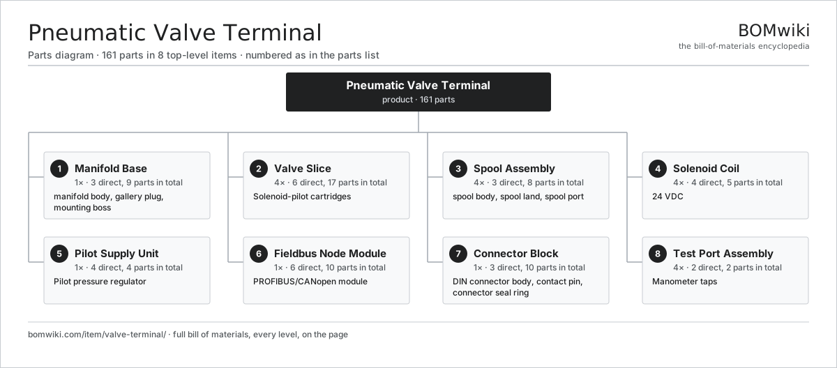
| # | Part | Qty | What it does |
|---|---|---|---|
| 1 | Manifold Base 3 parts | 1× | Aluminum or ductile-iron cavity block with ported galleries serving all valve slices. |
| 2 | Valve Slice 6 parts | 4× | Solenoid-pilot cartridges |
| 3 | Spool Assembly 3 parts | 4× | Precision-ported steel spool with lands that switch pressure between work ports. |
| 4 | Solenoid Coil 4 parts | 4× | 24 VDC |
| 5 | Pilot Supply Unit 4 parts | 1× | Pilot pressure regulator |
| 6 | Fieldbus Node Module 6 parts | 1× | PROFIBUS/CANopen module |
| 7 | Connector Block 3 parts | 1× | Multi-pin electrical interface for solenoid coils and sensor feedback. |
| 8 | Test Port Assembly 2 parts | 4× | Manometer taps |
3D model
No 3D model yet. Have a CAD file of this? Add a 3D model. STL renders right on this page; STEP, FreeCAD, and OpenSCAD sources are welcome too (openly licensed, like all 3D models on BOMwiki).
Build & assembly graph
expand / collapse · shared sub-assemblies converge · links to related products · est. labourTap an assembly to expand/collapse · tap a part to open it · use “Open page” for any node · drag to pan, scroll to zoom.
Bill of materials for Pneumatic Valve Terminal
8 top-level lines · 46 rows shown · 161 parts total · indented to 3 levels| # | Item / sub-assembly | Part no. | Qty/assy | Ext. qty | Parts | Type |
|---|---|---|---|---|---|---|
| 1 | Manifold Base 3 parts | valve-terminal-manifold-base | 1× | 1 | 9 | assembly |
| 1.1 | Manifold Body | valve-terminal-manifold-body | 1× | 1 | · | part |
| 1.2 | Gallery Plug | valve-terminal-gallery-plug | 6× | 6 | · | part |
| 1.3 | Mounting Boss | valve-terminal-mounting-boss | 2× | 2 | · | part |
| 2 | Valve Slice 6 parts | valve-terminal-valve-slice | 4× | 4 | 17 | assembly |
| 2.1 | Slice Body | valve-terminal-slice-body | 1× | 4 | · | part |
| 2.2 | Spool Assembly 3 parts | valve-terminal-spool-assembly | 1× | 4 | 8 | assembly |
| 2.2.1 | Spool Body | valve-terminal-spool-body | 1× | 4 | · | part |
| 2.2.2 | Spool Land | valve-terminal-spool-land | 3× | 12 | · | part |
| 2.2.3 | Spool Port | valve-terminal-spool-port | 4× | 16 | · | part |
| 2.3 | Solenoid Coil 4 parts | valve-terminal-solenoid-coil | 1× | 4 | 5 | assembly |
| 2.3.1 | Copper Winding | copper-winding | 1× | 4 | · | part |
| 2.3.2 | Coil Bobbin | valve-terminal-coil-bobbin | 1× | 4 | · | part |
| 2.3.3 | Terminal Pin | valve-terminal-coil-terminal | 2× | 8 | · | part |
| 2.3.4 | Plunger Armature | valve-terminal-plunger | 1× | 4 | · | part |
| 2.4 | Return Spring | valve-terminal-return-spring | 1× | 4 | · | part |
| 2.5 | Damping Nut | valve-terminal-damping-nut | 1× | 4 | · | part |
| 2.6 | O-Ring Set | oring-set | 1× | 4 | · | part |
| 3 | Spool Assembly 3 parts | valve-terminal-spool-assembly | 4× | 4 | 8 | assembly |
| 3.1 | Spool Body | valve-terminal-spool-body | 1× | 4 | · | part |
| 3.2 | Spool Land | valve-terminal-spool-land | 3× | 12 | · | part |
| 3.3 | Spool Port | valve-terminal-spool-port | 4× | 16 | · | part |
| 4 | Solenoid Coil 4 parts | valve-terminal-solenoid-coil | 4× | 4 | 5 | assembly |
| 4.1 | Copper Winding | copper-winding | 1× | 4 | · | part |
| 4.2 | Coil Bobbin | valve-terminal-coil-bobbin | 1× | 4 | · | part |
| 4.3 | Terminal Pin | valve-terminal-coil-terminal | 2× | 8 | · | part |
| 4.4 | Plunger Armature | valve-terminal-plunger | 1× | 4 | · | part |
| 5 | Pilot Supply Unit 4 parts | valve-terminal-pilot-supply | 1× | 1 | 4 | assembly |
| 5.1 | Pilot Filter Bowl | valve-terminal-pilot-filter | 1× | 1 | · | part |
| 5.2 | Pilot Regulator | valve-terminal-pilot-regulator | 1× | 1 | · | part |
| 5.3 | Pilot Gauge | valve-terminal-pilot-gauge | 1× | 1 | · | part |
| 5.4 | Pilot Relief Valve | valve-terminal-pilot-relief | 1× | 1 | · | part |
| 6 | Fieldbus Node Module 6 parts | valve-terminal-fieldbus-node | 1× | 1 | 10 | assembly |
| 6.1 | Bare PCB | pcb-bare | 1× | 1 | · | part |
| 6.2 | Fieldbus Gateway IC | valve-terminal-gateway-ic | 1× | 1 | · | part |
| 6.3 | MOSFET Driver | valve-terminal-mosfet-driver | 4× | 4 | · | part |
| 6.4 | Pressure Sensor | pressure-sensor | 2× | 2 | · | part |
| 6.5 | Microcontroller | mcu | 1× | 1 | · | part |
| 6.6 | Connector | connector | 1× | 1 | · | part |
| 7 | Connector Block 3 parts | valve-terminal-connector-block | 1× | 1 | 10 | assembly |
| 7.1 | DIN Connector Body | valve-terminal-din-connector | 1× | 1 | · | part |
| 7.2 | Contact Pin | valve-terminal-contact-pin | 8× | 8 | · | part |
| 7.3 | Connector Seal Ring | valve-terminal-sealing-ring | 1× | 1 | · | part |
| 8 | Test Port Assembly 2 parts | valve-terminal-test-ports | 4× | 4 | 2 | assembly |
| 8.1 | Test Adaptor | valve-terminal-test-adaptor | 1× | 4 | · | part |
| 8.2 | Test Filter | valve-terminal-test-filter | 1× | 4 | · | part |
Something wrong in this list? Report a problem with this BOM.
Related products
same domain, ranked by shared parts Control Valve
46 parts · shares 4 with this page
Hydraulic Test Bench
77 parts · shares 4 with this page
 Irrigation Pump Station
1,881 parts · shares 4 with this page
 Metering / Dosing Pump
44 parts · shares 4 with this page
Mine Dewatering Pump
259 parts · shares 4 with this page
 Centrifugal Compressor
338 parts · shares 3 with this page
Sourcing: possible vendors
Browse the supplier directory → Prices, MOQ, and lead times are algorithmic estimates, not quotes, and not claims about these companies. Company mappings are curated by keyword; est. price band $50–$50k. How estimates work| Vendor | HQ | Specialty | MOQ | Lead time |
|---|---|---|---|---|
|
🇩🇰Grundfos
grundfos.com ↗
|
Bjerringbro, DK | Pumps | 200 units | 6–12 wks |
|
🇺🇸Xylem
xylem.com ↗
|
Washington, US | Water technology | 200 units | 6–12 wks |
| flowserve.com ↗ | Irving, US | Pumps & valves | 200 units | 6–12 wks |
|
🇩🇪KSB
ksb.com ↗
|
Frankenthal, DE | Pumps & valves | 200 units | 6–12 wks |
| parker.com ↗ | Cleveland, US | Motion & fluid control | 200 units | 6–12 wks |
434-word article