Mainline Pipeline Pump
ProductOverview
A mainline pipeline pump is the machine that supplies the differential pressure needed to push crude oil or refined product through a long-distance transmission pipeline. Pump stations are placed every 50 to 150 km along the line; each station typically holds two to four of these units in series or parallel so that flow can continue while one unit is taken out for maintenance. The design shown here is a horizontal multistage barrel pump, classified as API 610 type BB5, where a forged outer barrel forms the pressure boundary and a removable inner cartridge holds the stacked stages.
The unit converts mechanical shaft power into fluid pressure through a series of impellers. Each Stage Impeller adds a fraction of the total head, and a six-stage rotor can develop more than 1,000 m of differential head. Because pipeline pressures reach 150 bar, the pressure boundary is a single forged Pressure Barrel rather than a split casing, which removes the long axial gasket joint that would otherwise be the weak point at high pressure.
How it works
Fluid enters through the suction nozzle in the Suction End Cover and is accelerated outward by the first impeller. It then passes into a vaned Stage Diffuser that converts velocity into static pressure and turns the flow inward toward the eye of the next impeller. This sequence repeats through every stage, so pressure climbs step by step from suction to discharge. After the final stage the fluid collects behind the Discharge End Cover and leaves through the discharge nozzle.
Each impeller produces an axial hydraulic force toward the suction end. In a multistage rotor these forces add up to a very large thrust that ordinary bearings could not carry. The Balance Drum solves this: discharge pressure acts on one face of the drum and a controlled leakage path bleeds pressure off the other face, producing a counter-force that cancels most of the stacked thrust. Only the residual is left for the Thrust Bearing to absorb.
Subsystems
The Rotating Element is the heart of the machine: a forged Pump Shaft carrying the impeller stack, renewable Wear Ring sets that control internal recirculation, and protective Shaft Sleeve elements under the seals. The whole cartridge slides out of the barrel from the rear, so the rotor can be overhauled in the shop while the barrel stays bolted to its piping.
The Bearing Housing uses a babbitt-lined Journal Bearing for radial load and a tilting-pad bearing for axial load, both fed by pressurized oil. Shaft sealing is handled by the Mechanical Seal System, a dual cartridge arrangement where a pressurized Barrier Fluid Seal Pot supplies clean barrier fluid between two seal faces. The barrier pressure is held above pump suction pressure so that any leakage is clean fluid inward, never crude outward.
Power reaches the pump through a Spacer Coupling with a drop-out Spacer Spool; removing the spool gives enough room to pull the seal cartridge without disturbing the driver alignment. The Lube Oil Skid is a separate skid with main and standby Lube Oil Pump units, a cooler, and duplex filters so oil flow never stops. The Condition Monitoring package watches shaft vibration with Vibration Probe pairs and bearing metal temperature with Bearing RTD elements, tripping the unit before damage occurs.
Materials
Pipeline service is not highly corrosive, so the wetted parts are usually carbon and low-alloy steel rather than exotic alloys. The barrel is a heavy steel forging rated for the full discharge pressure plus a margin for surge. The shaft is 42CrMo4 alloy steel for fatigue strength, and the impellers are cast in 12 percent chrome stainless such as CA6NM to resist erosion from entrained sand and water. The Seal Face components are silicon carbide, chosen for hardness and good dry-running tolerance during upset conditions. Disc packs in the coupling are 301 stainless for fatigue life under continuous flexing.
Variants
Stage count is the main variable: a short booster duty may need only two stages, while a high-head mountain crossing can use eight or more. Some stations specify a between-bearings double-suction first stage to lower the required NPSH when suction pressure is marginal. Drivers are most often two-pole induction motors, shown here as the Electric Motor Driver, but large stations sometimes use gas turbines or variable-speed drives. A variable-frequency drive lets the operator trim speed to match throughput, which saves significant energy compared with throttling a fixed-speed pump against a control valve.
Applications
These pumps move both crude gathering streams to refineries and finished products such as diesel and jet fuel along product pipelines. Series operation raises pressure at a single station; parallel operation raises flow. Because a tripped mainline pump can shut down an entire pipeline segment, reliability targets are severe, with mean time between repairs measured in years. Operators monitor the Mechanical Seal System and bearings continuously, and spare rotating cartridges are kept on the shelf so a unit can be returned to service within hours rather than weeks.
Mainline Pipeline Pump parts and their functions
9 top-level parts · 166 parts in total · full bill of materials below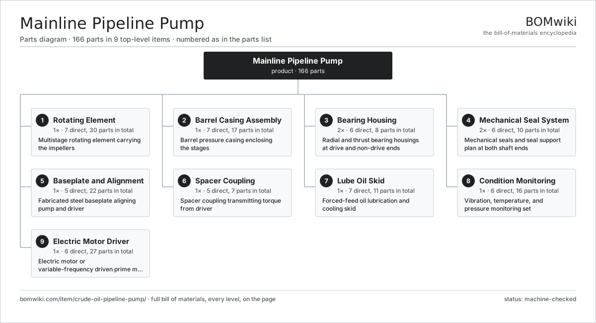
| # | Part | Qty | What it does |
|---|---|---|---|
| 1 | Rotating Element 7 parts | 1× | Multistage rotating element carrying the impellers |
| 2 | Barrel Casing Assembly 7 parts | 1× | Barrel pressure casing enclosing the stages |
| 3 | Bearing Housing 6 parts | 2× | Radial and thrust bearing housings at drive and non-drive ends |
| 4 | Mechanical Seal System 6 parts | 2× | Mechanical seals and seal support plan at both shaft ends |
| 5 | Baseplate and Alignment 5 parts | 1× | Fabricated steel baseplate aligning pump and driver |
| 6 | Spacer Coupling 5 parts | 1× | Spacer coupling transmitting torque from driver |
| 7 | Lube Oil Skid 7 parts | 1× | Forced-feed oil lubrication and cooling skid |
| 8 | Condition Monitoring 6 parts | 1× | Vibration, temperature, and pressure monitoring set |
| 9 | Electric Motor Driver 6 parts | 1× | Electric motor or variable-frequency driven prime mover |
3D model
No 3D model yet. Have a CAD file of this? Add a 3D model. STL renders right on this page; STEP, FreeCAD, and OpenSCAD sources are welcome too (openly licensed, like all 3D models on BOMwiki).
Build & assembly graph
expand / collapse · shared sub-assemblies converge · links to related products · est. labourTap an assembly to expand/collapse · tap a part to open it · use “Open page” for any node · drag to pan, scroll to zoom.
Bill of materials for Mainline Pipeline Pump
9 top-level lines · 71 rows shown · 166 parts total · indented to 3 levels| # | Item / sub-assembly | Part no. | Qty/assy | Ext. qty | Parts | Type |
|---|---|---|---|---|---|---|
| 1 | Rotating Element 7 parts | crude-oil-pipeline-pump-rotor | 1× | 1 | 30 | assembly |
| 1.1 | Pump Shaft | crude-oil-pipeline-pump-shaft | 1× | 1 | · | part |
| 1.2 | Stage Impeller | crude-oil-pipeline-pump-impeller | 6× | 6 | · | part |
| 1.3 | Wear Ring | crude-oil-pipeline-pump-wear-ring | 12× | 12 | · | part |
| 1.4 | Balance Drum | crude-oil-pipeline-pump-balance-drum | 1× | 1 | · | part |
| 1.5 | Shaft Sleeve | crude-oil-pipeline-pump-shaft-sleeve | 2× | 2 | · | part |
| 1.6 | Impeller Key | crude-oil-pipeline-pump-impeller-key | 6× | 6 | · | part |
| 1.7 | Shaft Lock Nut | crude-oil-pipeline-pump-lock-nut | 2× | 2 | · | part |
| 2 | Barrel Casing Assembly 7 parts | crude-oil-pipeline-pump-casing | 1× | 1 | 17 | assembly |
| 2.1 | Pressure Barrel | crude-oil-pipeline-pump-barrel | 1× | 1 | · | part |
| 2.2 | Stage Diffuser | crude-oil-pipeline-pump-diffuser | 6× | 6 | · | part |
| 2.3 | Stage Piece | crude-oil-pipeline-pump-stage-piece | 5× | 5 | · | part |
| 2.4 | Suction End Cover | crude-oil-pipeline-pump-suction-cover | 1× | 1 | · | part |
| 2.5 | Discharge End Cover | crude-oil-pipeline-pump-discharge-cover | 1× | 1 | · | part |
| 2.6 | Casing Gasket | crude-oil-pipeline-pump-casing-gasket | 2× | 2 | · | part |
| 2.7 | Fastener Set | fastener-set | 1× | 1 | · | part |
| 3 | Bearing Housing 6 parts | crude-oil-pipeline-pump-bearing-assembly | 2× | 2 | 8 | assembly |
| 3.1 | Journal Bearing | crude-oil-pipeline-pump-journal-bearing | 1× | 2 | · | part |
| 3.2 | Thrust Bearing | crude-oil-pipeline-pump-thrust-bearing | 1× | 2 | · | part |
| 3.3 | Bearing Housing Shell | crude-oil-pipeline-pump-bearing-housing-shell | 1× | 2 | · | part |
| 3.4 | Bearing Isolator | crude-oil-pipeline-pump-bearing-iso-seal | 2× | 4 | · | part |
| 3.5 | Oil Seal | oil-seal | 2× | 4 | · | part |
| 3.6 | Bearing Cooling Coil | crude-oil-pipeline-pump-cooling-coil | 1× | 2 | · | part |
| 4 | Mechanical Seal System 6 parts | crude-oil-pipeline-pump-seal-system | 2× | 2 | 10 | assembly |
| 4.1 | Seal Cartridge | crude-oil-pipeline-pump-seal-cartridge | 1× | 2 | · | part |
| 4.2 | Seal Face | crude-oil-pipeline-pump-seal-face | 2× | 4 | · | part |
| 4.3 | Seal Gland Plate | crude-oil-pipeline-pump-seal-gland | 1× | 2 | · | part |
| 4.4 | Barrier Fluid Seal Pot | crude-oil-pipeline-pump-seal-pot | 1× | 2 | · | part |
| 4.5 | O-Ring Set | oring-set | 1× | 2 | · | part |
| 4.6 | Coil Spring | coil-spring | 4× | 8 | · | part |
| 5 | Baseplate and Alignment 5 parts | crude-oil-pipeline-pump-baseplate | 1× | 1 | 22 | assembly |
| 5.1 | Base Fabrication | crude-oil-pipeline-pump-base-fabrication | 1× | 1 | · | part |
| 5.2 | Jacking Screw | crude-oil-pipeline-pump-jacking-screw | 8× | 8 | · | part |
| 5.3 | Shim Pack | crude-oil-pipeline-pump-shim-pack | 4× | 4 | · | part |
| 5.4 | Anchor Bolt | crude-oil-pipeline-pump-anchor-bolt | 8× | 8 | · | part |
| 5.5 | Drip Rim | crude-oil-pipeline-pump-drip-rim | 1× | 1 | · | part |
| 6 | Spacer Coupling 5 parts | crude-oil-pipeline-pump-coupling | 1× | 1 | 7 | assembly |
| 6.1 | Coupling Hub | crude-oil-pipeline-pump-coupling-hub | 2× | 2 | · | part |
| 6.2 | Disc Pack | crude-oil-pipeline-pump-disc-pack | 2× | 2 | · | part |
| 6.3 | Spacer Spool | crude-oil-pipeline-pump-spacer-spool | 1× | 1 | · | part |
| 6.4 | Coupling Guard | crude-oil-pipeline-pump-coupling-guard | 1× | 1 | · | part |
| 6.5 | Fastener Set | fastener-set | 1× | 1 | · | part |
| 7 | Lube Oil Skid 7 parts | crude-oil-pipeline-pump-lube-system | 1× | 1 | 11 | assembly |
| 7.1 | Oil Reservoir | crude-oil-pipeline-pump-oil-reservoir | 1× | 1 | · | part |
| 7.2 | Lube Oil Pump | crude-oil-pipeline-pump-lube-pump | 2× | 2 | · | part |
| 7.3 | Oil Cooler | crude-oil-pipeline-pump-oil-cooler | 1× | 1 | · | part |
| 7.4 | Oil Filter | crude-oil-pipeline-pump-oil-filter | 2× | 2 | · | part |
| 7.5 | Oil Piping | crude-oil-pipeline-pump-oil-piping | 1× | 1 | · | part |
| 7.6 | Pressure Sensor | pressure-sensor | 2× | 2 | · | part |
| 7.7 | Helical Gear Pair | gear-pair | 2× | 2 | · | part |
| 8 | Condition Monitoring 6 parts | crude-oil-pipeline-pump-instrumentation | 1× | 1 | 16 | assembly |
| 8.1 | Vibration Probe | crude-oil-pipeline-pump-vibration-probe | 4× | 4 | · | part |
| 8.2 | Bearing RTD | crude-oil-pipeline-pump-rtd | 4× | 4 | · | part |
| 8.3 | Pressure Sensor | pressure-sensor | 2× | 2 | · | part |
| 8.4 | Monitor Rack | crude-oil-pipeline-pump-monitor-rack | 1× | 1 | · | part |
| 8.5 | Relay | relay | 4× | 4 | · | part |
| 8.6 | Wire Bundle | wire-bundle | 1× | 1 | · | part |
| 9 | Electric Motor Driver 6 parts | crude-oil-pipeline-pump-driver | 1× | 1 | 27 | assembly |
| 9.1 | Stator Assembly 3 parts | stator-assembly | 1× | 1 | 3 | assembly |
| 9.1.1 | Stator Core (laminations) | stator-core | 1× | 1 | · | part |
| 9.1.2 | Copper Winding | copper-winding | 1× | 1 | · | part |
| 9.1.3 | Slot Insulation | stator-insulation | 1× | 1 | · | part |
| 9.2 | Rotor Assembly 4 parts | rotor-assembly | 1× | 1 | 19 | assembly |
| 9.2.1 | Rotor Shaft | rotor-shaft | 1× | 1 | · | part |
| 9.2.2 | Rotor Core | rotor-core | 1× | 1 | · | part |
| 9.2.3 | Neodymium Magnet | neodymium-magnet | 16× | 16 | · | part |
| 9.2.4 | Ball Bearing | ball-bearing | 1× | 1 | · | part |
| 9.3 | Motor Frame | crude-oil-pipeline-pump-motor-frame | 1× | 1 | · | part |
| 9.4 | Ball Bearing | ball-bearing | 2× | 2 | · | part |
| 9.5 | Motor Cooling Fan | crude-oil-pipeline-pump-motor-fan | 1× | 1 | · | part |
| 9.6 | Motor Terminal Box | crude-oil-pipeline-pump-motor-terminal-box | 1× | 1 | · | part |
Related products
same domain, ranked by shared parts Irrigation Pump Station
1,881 parts · shares 6 with this page
Irrigation Pump Station
1,881 parts · shares 6 with this page
 Hydraulic Power Unit
91 parts · shares 5 with this page
Hydraulic Power Unit
91 parts · shares 5 with this page
 Radial Spillway Gate
264 parts · shares 4 with this page
Radial Spillway Gate
264 parts · shares 4 with this page
 Ball Valve
61 parts · shares 3 with this page
Ball Valve
61 parts · shares 3 with this page
 Sluice Gate
123 parts · shares 3 with this page
Sluice Gate
123 parts · shares 3 with this page
 Air Compressor
97 parts · shares 3 with this page
Air Compressor
97 parts · shares 3 with this page
Sourcing: possible vendors
Browse the supplier directory → Prices, MOQ, and lead times are algorithmic estimates, not quotes, and not claims about these companies. Company mappings are curated by keyword; est. price band $50–$50k. How estimates work| Vendor | HQ | Specialty | MOQ | Lead time |
|---|---|---|---|---|
|
🇩🇰Grundfos
grundfos.com ↗
|
Bjerringbro, DK | Pumps | 200 units | 6–12 wks |
|
🇺🇸Xylem
xylem.com ↗
|
Washington, US | Water technology | 200 units | 6–12 wks |
| flowserve.com ↗ | Irving, US | Pumps & valves | 200 units | 6–12 wks |
|
🇩🇪KSB
ksb.com ↗
|
Frankenthal, DE | Pumps & valves | 200 units | 6–12 wks |
| parker.com ↗ | Cleveland, US | Motion & fluid control | 200 units | 6–12 wks |
924-word article