Sluice Gate
ProductOverview
A sluice gate is a sliding plate that opens and closes an opening in a canal, dam, channel or treatment basin to control how much water passes. The plate, called the leaf, slides up and down inside a fixed frame set into the concrete wall. Lower the leaf and it seals the opening; raise it and water flows under or through. Unlike a butterfly or knife valve in a closed pipe, a sluice gate works on an open or partly open waterway, and it is sized in metres of opening rather than in pipe diameter.
The product here is a fabricated rising-stem gate of the kind used on irrigation canals, dam outlet works and wastewater treatment plants. Its main groups are the Gate Leaf, the Guide Frame it slides in, the Seal Set that limit leakage, the Stem Assembly that drives it, the Headstock and Lift Mechanism that an operator turns, an optional Electric Actuator for remote control, and the Anchorage that ties everything into the structure.
How it works
Turning the Handwheel spins a bronze Lift Nut through a gear reduction. The nut threads onto the Threaded Stem, so as the nut turns the stem and the leaf attached to it move up or down. On a rising-stem gate the stem rises out of the headstock as the gate opens, and the exposed thread doubles as a position indicator. On a non-rising-stem gate the stem turns in place and a threaded lift nut built into the leaf travels along it, which suits cramped or submerged installations where a tall rising stem will not fit.
As the leaf reaches the closed position the Wedge Block faces ride up against matching wedges on the frame. They drive the leaf hard against the Frame Seal Seat, compressing the rubber seals and pulling leakage down. The same wedges must release cleanly on opening, which is why unseating a gate often needs as much thrust as seating it.
A key distinction is seating versus unseating head. Seating head pushes the leaf into the frame, so the seals are pressed tighter and the gate seals well. Unseating head pushes the leaf away from the frame, so the leaf must be held against its backing guides and the seals work harder. A gate rated for high seating head may carry a much lower unseating rating, and the data sheet lists both.
Subsystems
The Gate Leaf is a Skin Plate backed by horizontal Horizontal Stiffener Rib members that keep it from bowing under head. The Guide Frame embeds two Frame Jamb members, a Frame Head and an Invert Sill the leaf lands on. The Seal Set group carries side J-Seal strips, a top seal and a Bottom Seal at the invert, each held by a Seal Retainer Bar. The Headstock holds the Thrust Bearing that takes the axial load, plus a Position Indicator. Where the gate is automated, the Electric Actuator adds a motor, a worm Helical Gear Pair and a Control Board with Limit Switch and Position Sensor feedback to the plant SCADA.
Materials and construction
Frames and leaves are built either as grey cast iron, which is cheap and stiff for small gates, or as fabricated 304 or 316 stainless steel for corrosion service in wastewater, brackish water and coastal sites. Seal seats and the invert sill are faced in 316 stainless or bronze so they stay smooth against the rubber. Seals are EPDM for clean water or neoprene where oils and grease are present. Stems are stainless with rolled or cut ACME threads, sized so the unsupported length will not buckle under unseating thrust; tall stems run through Stem Guide Bracket brackets at intervals. Sliding side guides are bronze or UHMWPE so the leaf moves without galling.
Variants
Gates split by mounting and by stem. Wall-mounted gates bolt to a finished concrete face through an Embedment Plate; channel gates set directly into a formed slot. Flush-bottom gates seal the invert flat so sludge does not collect on the sill, which matters in wastewater channels. Weir gates and overflow gates spill water over the top of the leaf rather than under it. Drive options run from a simple handwheel, to a bench stand or floor stand for headroom, to a full electric Electric Actuator with Torque Limiter protection and remote operation.
Common failures
The usual problems are leakage and binding. Seal leakage comes from a hardened or torn J-Seal, from a Invert Sill worn by grit, or from a frame that has drifted out of plane during grouting. Binding comes from a bent stem, a dry Lift Nut, or debris jammed in the guides; an electric actuator will trip its Torque Limiter before it damages the stem. Corrosion attacks cast iron gates first at the waterline and at the fastener heads, which is why stainless or coated hardware is specified in aggressive water.
Selection and installation
Pick the gate by clear opening, by the higher of the seating and unseating heads, and by the leakage class the plant must meet under AWWA C560 for cast iron or C561 for stainless. Confirm the Anchor Bolt pattern against the wall opening and set the Embedment Plate true before grout. Install the frame plumb and square, shim it with Grout Shim pieces, grout it, then fit the leaf and adjust the Wedge Block faces so the seals compress evenly. Cycle the gate through full travel, check leakage at the rated head, and set the actuator limits and torque trips before handover.
Sluice Gate parts and their functions
8 top-level parts · 123 parts in total · full bill of materials below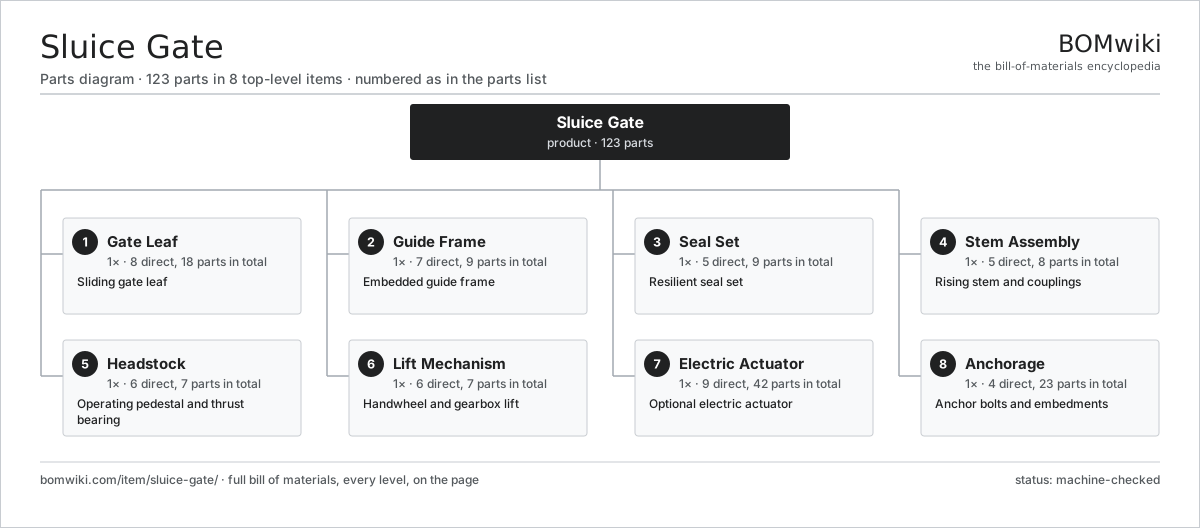
| # | Part | Qty | What it does |
|---|---|---|---|
| 1 | Gate Leaf 8 parts | 1× | Sliding gate leaf |
| 2 | Guide Frame 7 parts | 1× | Embedded guide frame |
| 3 | Seal Set 5 parts | 1× | Resilient seal set |
| 4 | Stem Assembly 5 parts | 1× | Rising stem and couplings |
| 5 | Headstock 6 parts | 1× | Operating pedestal and thrust bearing |
| 6 | Lift Mechanism 6 parts | 1× | Handwheel and gearbox lift |
| 7 | Electric Actuator 9 parts | 1× | Optional electric actuator |
| 8 | Anchorage 4 parts | 1× | Anchor bolts and embedments |
3D model
No 3D model yet. Have a CAD file of this? Add a 3D model. STL renders right on this page; STEP, FreeCAD, and OpenSCAD sources are welcome too (openly licensed, like all 3D models on BOMwiki).
Build & assembly graph
expand / collapse · shared sub-assemblies converge · links to related products · est. labourTap an assembly to expand/collapse · tap a part to open it · use “Open page” for any node · drag to pan, scroll to zoom.
Bill of materials for Sluice Gate
8 top-level lines · 74 rows shown · 123 parts total · indented to 3 levels| # | Item / sub-assembly | Part no. | Qty/assy | Ext. qty | Parts | Type |
|---|---|---|---|---|---|---|
| 1 | Gate Leaf 8 parts | sluice-gate-leaf | 1× | 1 | 18 | assembly |
| 1.1 | Skin Plate | sluice-gate-skin-plate | 1× | 1 | · | part |
| 1.2 | Horizontal Stiffener Rib | sluice-gate-stiffener-rib | 6× | 6 | · | part |
| 1.3 | Vertical Edge Rib | sluice-gate-vertical-rib | 2× | 2 | · | part |
| 1.4 | Seal Seating Bar | sluice-gate-seal-seat-leaf | 1× | 1 | · | part |
| 1.5 | Wedge Block | sluice-gate-wedge-block | 4× | 4 | · | part |
| 1.6 | Stem Thrust Pocket | sluice-gate-stem-pocket | 1× | 1 | · | part |
| 1.7 | Lifting Lug | sluice-gate-lifting-lug | 2× | 2 | · | part |
| 1.8 | Fastener Set | fastener-set | 1× | 1 | · | part |
| 2 | Guide Frame 7 parts | sluice-gate-guide-frame | 1× | 1 | 9 | assembly |
| 2.1 | Frame Jamb | sluice-gate-frame-jamb | 2× | 2 | · | part |
| 2.2 | Frame Head | sluice-gate-frame-head | 1× | 1 | · | part |
| 2.3 | Invert Sill | sluice-gate-invert-sill | 1× | 1 | · | part |
| 2.4 | Side Guide | sluice-gate-side-guide | 2× | 2 | · | part |
| 2.5 | Frame Seal Seat | sluice-gate-frame-seal-seat | 1× | 1 | · | part |
| 2.6 | Yoke Beam | sluice-gate-yoke | 1× | 1 | · | part |
| 2.7 | Fastener Set | fastener-set | 1× | 1 | · | part |
| 3 | Seal Set 5 parts | sluice-gate-seals | 1× | 1 | 9 | assembly |
| 3.1 | J-Seal | sluice-gate-j-seal | 2× | 2 | · | part |
| 3.2 | Top Seal | sluice-gate-top-seal | 1× | 1 | · | part |
| 3.3 | Bottom Seal | sluice-gate-bottom-seal | 1× | 1 | · | part |
| 3.4 | Seal Retainer Bar | sluice-gate-seal-retainer | 4× | 4 | · | part |
| 3.5 | Fastener Set | fastener-set | 1× | 1 | · | part |
| 4 | Stem Assembly 5 parts | sluice-gate-stem-assembly | 1× | 1 | 8 | assembly |
| 4.1 | Threaded Stem | sluice-gate-threaded-stem | 1× | 1 | · | part |
| 4.2 | Stem Coupling | sluice-gate-stem-coupling | 2× | 2 | · | part |
| 4.3 | Stem Guide Bracket | sluice-gate-stem-guide | 3× | 3 | · | part |
| 4.4 | Stem Cover Pipe | sluice-gate-stem-cover | 1× | 1 | · | part |
| 4.5 | Lift Nut | sluice-gate-stem-nut | 1× | 1 | · | part |
| 5 | Headstock 6 parts | sluice-gate-headstock | 1× | 1 | 7 | assembly |
| 5.1 | Pedestal Stand | sluice-gate-pedestal | 1× | 1 | · | part |
| 5.2 | Thrust Bearing | sluice-gate-thrust-bearing | 1× | 1 | · | part |
| 5.3 | Ball Bearing | ball-bearing | 1× | 1 | · | part |
| 5.4 | Position Indicator | sluice-gate-position-indicator | 1× | 1 | · | part |
| 5.5 | Grease Fitting | sluice-gate-grease-fitting | 2× | 2 | · | part |
| 5.6 | Fastener Set | fastener-set | 1× | 1 | · | part |
| 6 | Lift Mechanism 6 parts | sluice-gate-lift-mech | 1× | 1 | 7 | assembly |
| 6.1 | Handwheel | sluice-gate-handwheel | 1× | 1 | · | part |
| 6.2 | Helical Gear Pair | gear-pair | 1× | 1 | · | part |
| 6.3 | Gearbox Housing | gearbox-housing | 1× | 1 | · | part |
| 6.4 | Input Shaft | sluice-gate-input-shaft | 1× | 1 | · | part |
| 6.5 | Ball Bearing | ball-bearing | 2× | 2 | · | part |
| 6.6 | O-Ring Set | oring-set | 1× | 1 | · | part |
| 7 | Electric Actuator 9 parts | sluice-gate-actuator | 1× | 1 | 42 | assembly |
| 7.1 | Stator Assembly 3 parts | stator-assembly | 1× | 1 | 3 | assembly |
| 7.1.1 | Stator Core (laminations) | stator-core | 1× | 1 | · | part |
| 7.1.2 | Copper Winding | copper-winding | 1× | 1 | · | part |
| 7.1.3 | Slot Insulation | stator-insulation | 1× | 1 | · | part |
| 7.2 | Rotor Assembly 4 parts | rotor-assembly | 1× | 1 | 19 | assembly |
| 7.2.1 | Rotor Shaft | rotor-shaft | 1× | 1 | · | part |
| 7.2.2 | Rotor Core | rotor-core | 1× | 1 | · | part |
| 7.2.3 | Neodymium Magnet | neodymium-magnet | 16× | 16 | · | part |
| 7.2.4 | Ball Bearing | ball-bearing | 1× | 1 | · | part |
| 7.3 | Helical Gear Pair | gear-pair | 1× | 1 | · | part |
| 7.4 | Gearbox Housing | gearbox-housing | 1× | 1 | · | part |
| 7.5 | Ball Bearing | ball-bearing | 2× | 2 | · | part |
| 7.6 | O-Ring Set | oring-set | 1× | 1 | · | part |
| 7.7 | Torque Limiter | sluice-gate-torque-limiter | 1× | 1 | · | part |
| 7.8 | Control Board 9 parts | sluice-gate-control-board | 1× | 1 | 13 | assembly |
| 7.8.1 | Bare PCB | pcb-bare | 1× | 1 | · | part |
| 7.8.2 | Microcontroller | mcu | 1× | 1 | · | part |
| 7.8.3 | SMD Passive (R/C/L) | smd-passives | 1× | 1 | · | part |
| 7.8.4 | Relay | relay | 2× | 2 | · | part |
| 7.8.5 | Power Supply | power-supply | 1× | 1 | · | part |
| 7.8.6 | Limit Switch | sluice-gate-limit-switch | 2× | 2 | · | part |
| 7.8.7 | Position Sensor | sluice-gate-position-sensor | 1× | 1 | · | part |
| 7.8.8 | Connector | connector | 3× | 3 | · | part |
| 7.8.9 | Wire Bundle | wire-bundle | 1× | 1 | · | part |
| 7.9 | LCD Panel | lcd-panel | 1× | 1 | · | part |
| 8 | Anchorage 4 parts | sluice-gate-anchorage | 1× | 1 | 23 | assembly |
| 8.1 | Anchor Bolt | sluice-gate-anchor-bolt | 12× | 12 | · | part |
| 8.2 | Embedment Plate | sluice-gate-embedment-plate | 2× | 2 | · | part |
| 8.3 | Grout Shim | sluice-gate-grout-shim | 8× | 8 | · | part |
| 8.4 | Fastener Set | fastener-set | 1× | 1 | · | part |
Related products
same domain, ranked by shared parts Irrigation Pump Station
1,881 parts · shares 10 with this page
Irrigation Pump Station
1,881 parts · shares 10 with this page
 Radial Spillway Gate
264 parts · shares 8 with this page
Radial Spillway Gate
264 parts · shares 8 with this page
 Centrifugal Compressor
338 parts · shares 6 with this page
Centrifugal Compressor
338 parts · shares 6 with this page
 Ball Valve
61 parts · shares 7 with this page
Ball Valve
61 parts · shares 7 with this page
 Control Valve
46 parts · shares 5 with this page
Hydraulic Test Bench
77 parts · shares 5 with this page
Control Valve
46 parts · shares 5 with this page
Hydraulic Test Bench
77 parts · shares 5 with this page
Sourcing: possible vendors
Browse the supplier directory → Prices, MOQ, and lead times are algorithmic estimates, not quotes, and not claims about these companies. Company mappings are curated by keyword; est. price band $50–$50k. How estimates work| Vendor | HQ | Specialty | MOQ | Lead time |
|---|---|---|---|---|
|
🇩🇰Grundfos
grundfos.com ↗
|
Bjerringbro, DK | Pumps | 200 units | 6–12 wks |
|
🇺🇸Xylem
xylem.com ↗
|
Washington, US | Water technology | 200 units | 6–12 wks |
| flowserve.com ↗ | Irving, US | Pumps & valves | 200 units | 6–12 wks |
|
🇩🇪KSB
ksb.com ↗
|
Frankenthal, DE | Pumps & valves | 200 units | 6–12 wks |
| parker.com ↗ | Cleveland, US | Motion & fluid control | 200 units | 6–12 wks |
997-word article