Liquid-Ring Vacuum Pump
ProductOverview
A liquid-ring vacuum pump creates vacuum using a rotating ring of liquid, usually water, as a moving seal between an eccentric impeller and its casing. As the impeller spins, the liquid is flung outward into a ring that follows the casing bore; because the impeller is offset, the gap between the blades and the ring grows on one side and shrinks on the other, so each pocket between blades alternately draws gas in and squeezes it out. It is the workhorse vacuum pump for wet and dirty duties, paper machines, condenser exhausting, food and chemical processing, filtration and distillation, because it tolerates carryover of vapor, droplets and slurry that would damage a dry pump.
The liquid does triple duty: it forms the compression seal, absorbs the heat of compression so the discharge stays near-isothermal, and condenses some of the pumped vapor. The trade-off is that the achievable vacuum is limited by the vapor pressure of the service liquid, so cold water gives deeper vacuum than warm.
How it works
Process gas enters and leaves through ports in the Ported Cone at the center of the Pump Casing. The Rotor Assembly spins eccentrically inside that casing; its forward-curved Liquid-Ring Impeller throws the service liquid into a ring against the bore, and the changing pocket volume between the blades draws gas in over the inlet port and compresses it over the discharge port. Make-up sealing water arrives through the Service Liquid Inlet inlet, where a flow orifice meters it and a check valve guards against suck-back on shutdown.
The rotating shaft is carried on the Bearing Set and sealed where it leaves the casing by the Mechanical Seal, whose lapped faces keep service liquid in and air out. Power comes from the Drive Motor through a flexible Drive Coupling, so the motor and pump can be aligned independently on the Base Frame / Skid.
What the pump discharges is a frothy mix of gas and entrained water. The Discharge Separator knocks that liquid out so clean gas vents and the water can be drained or recirculated. Operators read suction vacuum and liquid temperature from the Gauge Panel, the two numbers that together tell whether the ring is healthy and the pump is reaching its rated vacuum.
Liquid-Ring Vacuum Pump parts and their functions
10 top-level parts · 60 parts in total · full bill of materials below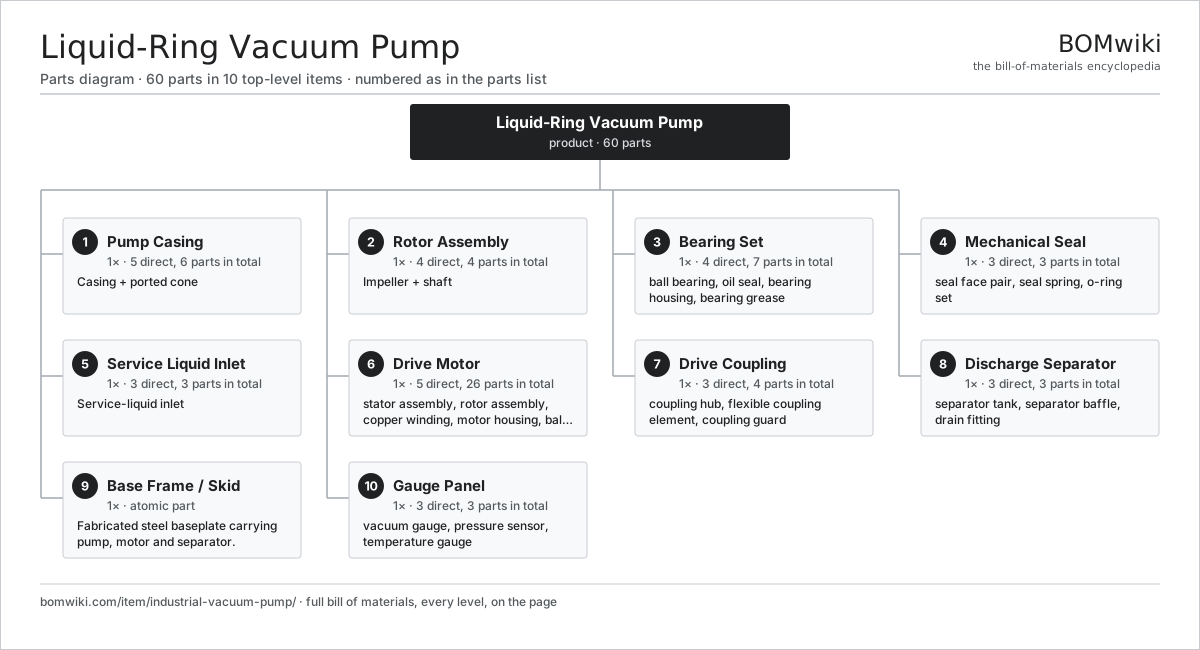
| # | Part | Qty | What it does |
|---|---|---|---|
| 1 | Pump Casing 5 parts | 1× | Casing + ported cone |
| 2 | Rotor Assembly 4 parts | 1× | Impeller + shaft |
| 3 | Bearing Set 4 parts | 1× | Radial ball bearings with shaft oil seals at each end. |
| 4 | Mechanical Seal 3 parts | 1× | Single mechanical seal sealing the shaft where it leaves the casing. |
| 5 | Service Liquid Inlet 3 parts | 1× | Service-liquid inlet |
| 6 | Drive Motor 5 parts | 1× | Foot-mounted induction motor driving the pump shaft. |
| 7 | Drive Coupling 3 parts | 1× | |
| 8 | Discharge Separator 3 parts | 1× | Knock-out vessel that separates the discharged gas from the service liquid. |
| 9 | Base Frame / Skid | 1× | Fabricated steel baseplate carrying pump, motor and separator. |
| 10 | Gauge Panel 3 parts | 1× |
3D model
No 3D model yet. Have a CAD file of this? Add a 3D model. STL renders right on this page; STEP, FreeCAD, and OpenSCAD sources are welcome too (openly licensed, like all 3D models on BOMwiki).
Build & assembly graph
expand / collapse · shared sub-assemblies converge · links to related products · est. labourTap an assembly to expand/collapse · tap a part to open it · use “Open page” for any node · drag to pan, scroll to zoom.
Bill of materials for Liquid-Ring Vacuum Pump
10 top-level lines · 50 rows shown · 60 parts total · indented to 3 levels| # | Item / sub-assembly | Part no. | Qty/assy | Ext. qty | Parts | Type |
|---|---|---|---|---|---|---|
| 1 | Pump Casing 5 parts | industrial-vacuum-pump-casing | 1× | 1 | 6 | assembly |
| 1.1 | Casing Body | industrial-vacuum-pump-casing-body | 1× | 1 | · | part |
| 1.2 | Ported Cone | industrial-vacuum-pump-cone | 1× | 1 | · | part |
| 1.3 | Head Plate | industrial-vacuum-pump-head-plate | 2× | 2 | · | part |
| 1.4 | O-Ring Set | oring-set | 1× | 1 | · | part |
| 1.5 | Fastener Set | fastener-set | 1× | 1 | · | part |
| 2 | Rotor Assembly 4 parts | industrial-vacuum-pump-rotor | 1× | 1 | 4 | assembly |
| 2.1 | Liquid-Ring Impeller | industrial-vacuum-pump-impeller | 1× | 1 | · | part |
| 2.2 | Pump Shaft | industrial-vacuum-pump-shaft | 1× | 1 | · | part |
| 2.3 | Shaft Sleeve | industrial-vacuum-pump-shaft-sleeve | 1× | 1 | · | part |
| 2.4 | Impeller Key | industrial-vacuum-pump-impeller-key | 1× | 1 | · | part |
| 3 | Bearing Set 4 parts | industrial-vacuum-pump-bearing-set | 1× | 1 | 7 | assembly |
| 3.1 | Ball Bearing | ball-bearing | 2× | 2 | · | part |
| 3.2 | Oil Seal | oil-seal | 2× | 2 | · | part |
| 3.3 | Bearing Housing | industrial-vacuum-pump-bearing-housing | 2× | 2 | · | part |
| 3.4 | Bearing Grease | industrial-vacuum-pump-bearing-grease | 1× | 1 | · | part |
| 4 | Mechanical Seal 3 parts | industrial-vacuum-pump-mech-seal | 1× | 1 | 3 | assembly |
| 4.1 | Seal Face Pair | industrial-vacuum-pump-seal-faces | 1× | 1 | · | part |
| 4.2 | Seal Spring | industrial-vacuum-pump-seal-spring | 1× | 1 | · | part |
| 4.3 | O-Ring Set | oring-set | 1× | 1 | · | part |
| 5 | Service Liquid Inlet 3 parts | industrial-vacuum-pump-service-liquid | 1× | 1 | 3 | assembly |
| 5.1 | Liquid Inlet Connection | industrial-vacuum-pump-liquid-inlet | 1× | 1 | · | part |
| 5.2 | Flow Orifice | industrial-vacuum-pump-flow-orifice | 1× | 1 | · | part |
| 5.3 | Vacuum Check Valve | industrial-vacuum-pump-check-valve | 1× | 1 | · | part |
| 6 | Drive Motor 5 parts | industrial-vacuum-pump-drive-motor | 1× | 1 | 26 | assembly |
| 6.1 | Stator Assembly 3 parts | stator-assembly | 1× | 1 | 3 | assembly |
| 6.1.1 | Stator Core (laminations) | stator-core | 1× | 1 | · | part |
| 6.1.2 | Copper Winding | copper-winding | 1× | 1 | · | part |
| 6.1.3 | Slot Insulation | stator-insulation | 1× | 1 | · | part |
| 6.2 | Rotor Assembly 4 parts | rotor-assembly | 1× | 1 | 19 | assembly |
| 6.2.1 | Rotor Shaft | rotor-shaft | 1× | 1 | · | part |
| 6.2.2 | Rotor Core | rotor-core | 1× | 1 | · | part |
| 6.2.3 | Neodymium Magnet | neodymium-magnet | 16× | 16 | · | part |
| 6.2.4 | Ball Bearing | ball-bearing | 1× | 1 | · | part |
| 6.3 | Copper Winding | copper-winding | 1× | 1 | · | part |
| 6.4 | Motor Housing | motor-housing | 1× | 1 | · | part |
| 6.5 | Ball Bearing | ball-bearing | 2× | 2 | · | part |
| 7 | Drive Coupling 3 parts | industrial-vacuum-pump-coupling | 1× | 1 | 4 | assembly |
| 7.1 | Coupling Hub | industrial-vacuum-pump-coupling-hub | 2× | 2 | · | part |
| 7.2 | Flexible Coupling Element | industrial-vacuum-pump-coupling-element | 1× | 1 | · | part |
| 7.3 | Coupling Guard | industrial-vacuum-pump-coupling-guard | 1× | 1 | · | part |
| 8 | Discharge Separator 3 parts | industrial-vacuum-pump-separator | 1× | 1 | 3 | assembly |
| 8.1 | Separator Tank | industrial-vacuum-pump-separator-tank | 1× | 1 | · | part |
| 8.2 | Separator Baffle | industrial-vacuum-pump-baffle | 1× | 1 | · | part |
| 8.3 | Drain Fitting | industrial-vacuum-pump-drain-fitting | 1× | 1 | · | part |
| 9 | Base Frame / Skid | industrial-vacuum-pump-base-frame | 1× | 1 | · | part |
| 10 | Gauge Panel 3 parts | industrial-vacuum-pump-gauges | 1× | 1 | 3 | assembly |
| 10.1 | Vacuum Gauge | industrial-vacuum-pump-vac-gauge | 1× | 1 | · | part |
| 10.2 | Pressure Sensor | pressure-sensor | 1× | 1 | · | part |
| 10.3 | Temperature Gauge | industrial-vacuum-pump-temp-gauge | 1× | 1 | · | part |
Something wrong in this list? Report a problem with this BOM.
Related products
same domain, ranked by shared parts Centrifugal Compressor
338 parts · shares 3 with this page
 High-Pressure Plunger Pump
115 parts · shares 3 with this page
 Hydraulic Power Unit
91 parts · shares 3 with this page
 Radial Spillway Gate
264 parts · shares 3 with this page
 Boiler Feedwater Pump
169 parts · shares 2 with this page
 Hydraulic Cylinder
17 parts · shares 2 with this page
Sourcing: possible vendors
Browse the supplier directory → Prices, MOQ, and lead times are algorithmic estimates, not quotes, and not claims about these companies. Company mappings are curated by keyword; est. price band $50–$50k. How estimates work| Vendor | HQ | Specialty | MOQ | Lead time |
|---|---|---|---|---|
|
🇩🇰Grundfos
grundfos.com ↗
|
Bjerringbro, DK | Pumps | 200 units | 6–12 wks |
|
🇺🇸Xylem
xylem.com ↗
|
Washington, US | Water technology | 200 units | 6–12 wks |
| flowserve.com ↗ | Irving, US | Pumps & valves | 200 units | 6–12 wks |
|
🇩🇪KSB
ksb.com ↗
|
Frankenthal, DE | Pumps & valves | 200 units | 6–12 wks |
| parker.com ↗ | Cleveland, US | Motion & fluid control | 200 units | 6–12 wks |
407-word article