Air Compressor
ProductOverview
This package is an oil-injected rotary screw air compressor, the workhorse of industrial compressed-air supply. A pair of meshing helical rotors continuously draws in and compresses atmospheric air, delivering a smooth, pulsation-free flow rather than the cyclic output of a piston machine. Oil injected into the compression chamber seals the rotor clearances, removes the heat of compression, and lubricates the bearings. The complete unit mounts inside an acoustic canopy with its motor, cooling, oil separation and controls integrated as a turnkey skid.
How it works
Ambient air enters through the Air Intake Assembly, where a filter and unloader valve regulate flow on demand. It passes into the Airend (Compression Element), the heart of the machine, where the male and female rotors mesh and progressively reduce the trapped volume to raise pressure. The Drive Motor turns the airend through a direct Drive Coupling, avoiding belt losses and maintenance.
Compressed air leaves the airend carrying entrained oil. The Oil System circulates lubricant through a thermostatic valve, cooler and filter, while the Aftercooler & Moisture Separator section uses an aftercooler and separator to strip oil mist from the air and drop its temperature close to ambient before it reaches the plant. A Minimum Pressure / Check Valve holds receiver pressure during start-up and prevents reverse flow at shutdown.
Heat is rejected by the Cooling Fan Assembly, which draws cooling air across the oil and air coolers. The Controller manages load/unload cycling, monitors discharge temperature and pressure, and protects the airend from over-temperature trips. Power distribution, the starter and motor protection live in the Electrical Panel section. Everything is wrapped in the Canopy / Enclosure, whose acoustic lining keeps operating noise low enough for installation on the shop floor without a dedicated compressor room.
Air Compressor parts and their functions
11 top-level parts · 97 parts in total · full bill of materials below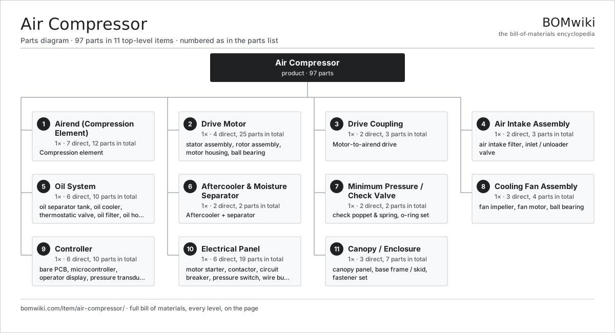
| # | Part | Qty | What it does |
|---|---|---|---|
| 1 | Airend (Compression Element) 7 parts | 1× | Compression element |
| 2 | Drive Motor 4 parts | 1× | TEFC induction motor driving the airend. |
| 3 | Drive Coupling 2 parts | 1× | Motor-to-airend drive |
| 4 | Air Intake Assembly 2 parts | 1× | |
| 5 | Oil System 6 parts | 1× | Separates, cools, filters and meters the injection oil. |
| 6 | Aftercooler & Moisture Separator 2 parts | 1× | Aftercooler + separator |
| 7 | Minimum Pressure / Check Valve 2 parts | 1× | Holds line pressure above the separation minimum and blocks backflow. |
| 8 | Cooling Fan Assembly 3 parts | 1× | Draws ambient air across the oil cooler and aftercooler. |
| 9 | Controller 6 parts | 1× | Microcontroller-based load/unload and protection controller. |
| 10 | Electrical Panel 6 parts | 1× | |
| 11 | Canopy / Enclosure 3 parts | 1× |
Diagrams & photos


3D model
No 3D model yet. Have a CAD file of this? Add a 3D model. STL renders right on this page; STEP, FreeCAD, and OpenSCAD sources are welcome too (openly licensed, like all 3D models on BOMwiki).
Build & assembly graph
expand / collapse · shared sub-assemblies converge · links to related products · est. labourTap an assembly to expand/collapse · tap a part to open it · use “Open page” for any node · drag to pan, scroll to zoom.
Bill of materials for Air Compressor
11 top-level lines · 65 rows shown · 97 parts total · indented to 3 levels| # | Item / sub-assembly | Part no. | Qty/assy | Ext. qty | Parts | Type |
|---|---|---|---|---|---|---|
| 1 | Airend (Compression Element) 7 parts | air-compressor-airend | 1× | 1 | 12 | assembly |
| 1.1 | Airend Housing | air-compressor-airend-housing | 1× | 1 | · | part |
| 1.2 | Male Rotor | air-compressor-male-rotor | 1× | 1 | · | part |
| 1.3 | Female Rotor | air-compressor-female-rotor | 1× | 1 | · | part |
| 1.4 | Ball Bearing | ball-bearing | 4× | 4 | · | part |
| 1.5 | Thrust Bearing | air-compressor-thrust-bearing | 2× | 2 | · | part |
| 1.6 | Oil Seal | oil-seal | 2× | 2 | · | part |
| 1.7 | O-Ring Set | oring-set | 1× | 1 | · | part |
| 2 | Drive Motor 4 parts | air-compressor-drive-motor | 1× | 1 | 25 | assembly |
| 2.1 | Stator Assembly 3 parts | stator-assembly | 1× | 1 | 3 | assembly |
| 2.1.1 | Stator Core (laminations) | stator-core | 1× | 1 | · | part |
| 2.1.2 | Copper Winding | copper-winding | 1× | 1 | · | part |
| 2.1.3 | Slot Insulation | stator-insulation | 1× | 1 | · | part |
| 2.2 | Rotor Assembly 4 parts | rotor-assembly | 1× | 1 | 19 | assembly |
| 2.2.1 | Rotor Shaft | rotor-shaft | 1× | 1 | · | part |
| 2.2.2 | Rotor Core | rotor-core | 1× | 1 | · | part |
| 2.2.3 | Neodymium Magnet | neodymium-magnet | 16× | 16 | · | part |
| 2.2.4 | Ball Bearing | ball-bearing | 1× | 1 | · | part |
| 2.3 | Motor Housing | motor-housing | 1× | 1 | · | part |
| 2.4 | Ball Bearing | ball-bearing | 2× | 2 | · | part |
| 3 | Drive Coupling 2 parts | air-compressor-coupling | 1× | 1 | 3 | assembly |
| 3.1 | Coupling Hub | air-compressor-coupling-hub | 2× | 2 | · | part |
| 3.2 | Flexible Coupling Element | air-compressor-coupling-element | 1× | 1 | · | part |
| 4 | Air Intake Assembly 2 parts | air-compressor-intake | 1× | 1 | 3 | assembly |
| 4.1 | Air Intake Filter | air-compressor-air-filter | 1× | 1 | · | part |
| 4.2 | Inlet / Unloader Valve 2 parts | air-compressor-inlet-valve | 1× | 1 | 2 | assembly |
| 4.2.1 | Valve Piston | air-compressor-valve-piston | 1× | 1 | · | part |
| 4.2.2 | O-Ring Set | oring-set | 1× | 1 | · | part |
| 5 | Oil System 6 parts | air-compressor-oil-system | 1× | 1 | 10 | assembly |
| 5.1 | Oil Separator Tank 2 parts | air-compressor-oil-separator | 1× | 1 | 2 | assembly |
| 5.1.1 | Separator Element | air-compressor-separator-element | 1× | 1 | · | part |
| 5.1.2 | O-Ring Set | oring-set | 1× | 1 | · | part |
| 5.2 | Oil Cooler | air-compressor-oil-cooler | 1× | 1 | · | part |
| 5.3 | Thermostatic Valve | air-compressor-thermostatic-valve | 1× | 1 | · | part |
| 5.4 | Oil Filter | air-compressor-oil-filter | 1× | 1 | · | part |
| 5.5 | Oil Hose | air-compressor-oil-hose | 4× | 4 | · | part |
| 5.6 | Compressor Oil | air-compressor-compressor-oil | 1× | 1 | · | part |
| 6 | Aftercooler & Moisture Separator 2 parts | air-compressor-air-cooling | 1× | 1 | 2 | assembly |
| 6.1 | Air Aftercooler | air-compressor-aftercooler | 1× | 1 | · | part |
| 6.2 | Moisture Separator | air-compressor-moisture-separator | 1× | 1 | · | part |
| 7 | Minimum Pressure / Check Valve 2 parts | air-compressor-min-pressure-valve | 1× | 1 | 2 | assembly |
| 7.1 | Check Poppet & Spring | air-compressor-mpv-poppet | 1× | 1 | · | part |
| 7.2 | O-Ring Set | oring-set | 1× | 1 | · | part |
| 8 | Cooling Fan Assembly 3 parts | air-compressor-cooling-fan | 1× | 1 | 4 | assembly |
| 8.1 | Fan Impeller | air-compressor-fan-blade | 1× | 1 | · | part |
| 8.2 | Fan Motor | air-compressor-fan-motor | 1× | 1 | · | part |
| 8.3 | Ball Bearing | ball-bearing | 2× | 2 | · | part |
| 9 | Controller 6 parts | air-compressor-controller | 1× | 1 | 10 | assembly |
| 9.1 | Bare PCB | pcb-bare | 1× | 1 | · | part |
| 9.2 | Microcontroller | mcu | 1× | 1 | · | part |
| 9.3 | Operator Display | air-compressor-display | 1× | 1 | · | part |
| 9.4 | Pressure Transducer | air-compressor-pressure-transducer | 1× | 1 | · | part |
| 9.5 | Temperature Sensor | air-compressor-temp-sensor | 2× | 2 | · | part |
| 9.6 | Relay | relay | 4× | 4 | · | part |
| 10 | Electrical Panel 6 parts | air-compressor-electrical | 1× | 1 | 19 | assembly |
| 10.1 | Motor Starter | air-compressor-starter | 1× | 1 | · | part |
| 10.2 | Contactor | air-compressor-contactor | 3× | 3 | · | part |
| 10.3 | Circuit Breaker | air-compressor-circuit-breaker | 1× | 1 | · | part |
| 10.4 | Pressure Switch | pressure-switch | 1× | 1 | · | part |
| 10.5 | Wire Bundle | wire-bundle | 1× | 1 | · | part |
| 10.6 | Connector | connector | 12× | 12 | · | part |
| 11 | Canopy / Enclosure 3 parts | air-compressor-canopy | 1× | 1 | 7 | assembly |
| 11.1 | Canopy Panel | air-compressor-canopy-panel | 5× | 5 | · | part |
| 11.2 | Base Frame / Skid | air-compressor-base-frame | 1× | 1 | · | part |
| 11.3 | Fastener Set | fastener-set | 1× | 1 | · | part |
Something wrong in this list? Report a problem with this BOM.
Related products
same domain, ranked by shared parts Centrifugal Pump
66 parts · shares 7 with this page
 Submersible Pump
84 parts · shares 7 with this page
 Irrigation Pump Station
1,881 parts · shares 6 with this page
 Ball Valve
61 parts · shares 6 with this page
 Sluice Gate
123 parts · shares 5 with this page
 Radial Spillway Gate
264 parts · shares 5 with this page
Sourcing: possible vendors
Browse the supplier directory → Prices, MOQ, and lead times are algorithmic estimates, not quotes, and not claims about these companies. Company mappings are curated by keyword; est. price band $50–$50k. How estimates work| Vendor | HQ | Specialty | MOQ | Lead time |
|---|---|---|---|---|
|
🇩🇰Grundfos
grundfos.com ↗
|
Bjerringbro, DK | Pumps | 200 units | 6–12 wks |
|
🇺🇸Xylem
xylem.com ↗
|
Washington, US | Water technology | 200 units | 6–12 wks |
| flowserve.com ↗ | Irving, US | Pumps & valves | 200 units | 6–12 wks |
|
🇩🇪KSB
ksb.com ↗
|
Frankenthal, DE | Pumps & valves | 200 units | 6–12 wks |
| parker.com ↗ | Cleveland, US | Motion & fluid control | 200 units | 6–12 wks |
306-word article