Radial Spillway Gate
ProductOverview
A radial spillway gate, also called a Tainter gate, is a curved steel gate that controls the release of flood water over the crest of a dam spillway. The gate sits between two concrete piers and pivots about a horizontal trunnion pin downstream of the water-retaining face. When closed it holds back the reservoir; when the hoist raises it, water passes underneath in a controlled surface discharge over the spillway crest. Radial gates are the dominant choice for large spillways because the curved face routes the entire water load through the radial arms into the trunnion, so the gate can be very large yet still operated by a modest hoist.
The water-retaining surface is the curved skin plate, a cylindrical steel face whose center of curvature lies exactly on the trunnion pin axis. Because every point of the face is the same distance from the pin, the hydrostatic pressure acting normal to the plate produces a resultant force that points straight at the pin. That geometry is the whole reason the design works.
How it works
Water pressure increases linearly with depth, so the load on the skin plate is largest at the bottom and zero at the surface. The plate alone is thin, so a stiffening grid of horizontal girders and vertical ribs backs it up and collects the distributed pressure into a few concentrated line loads. The horizontal girders carry these loads across the span to the two sets of radial arms.
To open the gate, the motor drives the gearbox and rope drums, which reel in the wire ropes attached to the gate. The whole gate rotates about the trunnion pin, lifting its lower lip clear of the sill and letting water spill underneath. Discharge is metered by the gate opening and the reservoir level, which the level sensor feeds to the control system so releases can track the inflow hydrograph.
Trunnion and load path
The defining feature of a radial gate is its load path. Because the face is cylindrical about the trunnion pin, the resultant of all the hydrostatic pressure passes through the pin axis. The two arm struts of each set act almost purely in compression, carrying that resultant from the girders to the trunnion hub. The pin then reacts the entire thrust, which can reach 3 to 40 MN depending on gate size, in double shear, and passes it through the trunnion bracket and embedded girder into the concrete pier.
Two consequences follow. First, the thrust line passes through the pivot, so it creates almost no moment about the trunnion. The hoist therefore only has to overcome the gate self-weight, the trunnion friction, and the seal friction, not the water load. That is why a gate retaining tens of meganewtons can be lifted by a hoist rated at a few hundred kilonewtons per arm. Second, the trunnion bushing runs at very high contact pressure but low sliding speed, so a self-lubricating aluminium-bronze bushing is used and the friction coefficient is kept low to limit hoist load.
Materials and construction
The skin plate, girders, ribs, and arms are fabricated from weldable structural steel, typically ASTM A572 Grade 50 or S355J2, and shop-assembled in segments that are field-bolted at the arm flanges. The trunnion pin is a forged alloy steel pin, 200 to 500 mm in diameter, machined and ground to run in the bronze bushings. All submerged steel carries a zinc-rich epoxy and polyurethane coating, since the steel cycles between wet and dry and corrosion at the trunnion or seals is a common cause of hard operation.
Sealing is by rubber. Music-note side seals run up each side of the gate and are pressed by water pressure against the polished stainless rubbing plates embedded in the piers. A J-seal along the lower lip seats on the sill plate when closed. The seals are held by clamp bars that set the seal projection, which is adjusted in the field to balance tight sealing against hoist friction.
The trunnion reaction is anchored into the pier by the anchorage, usually a combination of the embedded trunnion girder and post-tensioned anchor tendons that prestress the concrete so it stays in compression under the gate thrust.
Variants
The hoist can be a wire-rope drum hoist, as detailed here, or a pair of hydraulic cylinders acting on the arms. Cylinders give precise position control and are common on newer or remotely operated gates, while rope hoists are simple and easy to service. Submergible designs place the trunnion below tailwater for very large gates. Cold-climate gates add the de-icing system, with trace heaters along the seals and trunnion so ice does not freeze the gate to the sill or seize the bushing. Most large gates are automated through the control system, with a PLC, position encoder, and limit switches that hold a target opening or follow a reservoir-level schedule.
Common failures
The trunnion is the critical element. If the bushing corrodes or loses lubrication, friction rises sharply, the hoist can stall, and in severe cases the arms have buckled when the bushing seized and the rising hoist force overloaded them. Regular greasing through the grease fittings and friction monitoring are essential. Seal wear and hardening cause leakage and higher operating effort; seals are wear items replaced on a schedule. Corrosion of the anchor tendons or loss of prestress threatens the load path into the pier and is checked by inspection and tendon lift-off testing. Wire-rope corrosion, brake faults, and limit-switch failures are the typical hoist problems, which is why the brake is spring-set so the gate holds position on power loss.
Radial Spillway Gate parts and their functions
10 top-level parts · 264 parts in total · full bill of materials below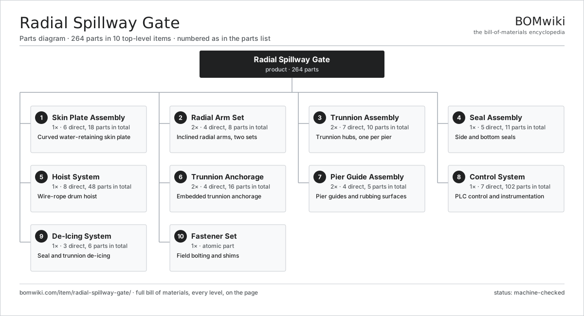
| # | Part | Qty | What it does |
|---|---|---|---|
| 1 | Skin Plate Assembly 6 parts | 1× | Curved water-retaining skin plate |
| 2 | Radial Arm Set 4 parts | 2× | Inclined radial arms, two sets |
| 3 | Trunnion Assembly 7 parts | 2× | Trunnion hubs, one per pier |
| 4 | Seal Assembly 5 parts | 1× | Side and bottom seals |
| 5 | Hoist System 8 parts | 1× | Wire-rope drum hoist |
| 6 | Trunnion Anchorage 4 parts | 2× | Embedded trunnion anchorage |
| 7 | Pier Guide Assembly 4 parts | 2× | Pier guides and rubbing surfaces |
| 8 | Control System 7 parts | 1× | PLC control and instrumentation |
| 9 | De-Icing System 3 parts | 1× | Seal and trunnion de-icing |
| 10 | Fastener Set | 1× | Field bolting and shims |
3D model
No 3D model yet. Have a CAD file of this? Add a 3D model. STL renders right on this page; STEP, FreeCAD, and OpenSCAD sources are welcome too (openly licensed, like all 3D models on BOMwiki).
Build & assembly graph
expand / collapse · shared sub-assemblies converge · links to related products · est. labourTap an assembly to expand/collapse · tap a part to open it · use “Open page” for any node · drag to pan, scroll to zoom.
Bill of materials for Radial Spillway Gate
10 top-level lines · 75 rows shown · 264 parts total · indented to 3 levels| # | Item / sub-assembly | Part no. | Qty/assy | Ext. qty | Parts | Type |
|---|---|---|---|---|---|---|
| 1 | Skin Plate Assembly 6 parts | radial-spillway-gate-skin-plate-assy | 1× | 1 | 18 | assembly |
| 1.1 | Curved Skin Plate | radial-spillway-gate-skin-plate | 1× | 1 | · | part |
| 1.2 | Horizontal Girder | radial-spillway-gate-horizontal-girder | 4× | 4 | · | part |
| 1.3 | Vertical Rib | radial-spillway-gate-vertical-rib | 8× | 8 | · | part |
| 1.4 | End Plate | radial-spillway-gate-end-plate | 2× | 2 | · | part |
| 1.5 | Lifting Lug | radial-spillway-gate-lifting-lug | 2× | 2 | · | part |
| 1.6 | Corrosion Coating System | radial-spillway-gate-corrosion-coating | 1× | 1 | · | part |
| 2 | Radial Arm Set 4 parts | radial-spillway-gate-arm-assy | 2× | 2 | 8 | assembly |
| 2.1 | Radial Arm Strut | radial-spillway-gate-arm-strut | 2× | 4 | · | part |
| 2.2 | Arm Bracing Member | radial-spillway-gate-arm-bracing | 3× | 6 | · | part |
| 2.3 | Arm Connection Flange | radial-spillway-gate-arm-flange | 2× | 4 | · | part |
| 2.4 | Arm Hub Gusset | radial-spillway-gate-arm-hub-plate | 1× | 2 | · | part |
| 3 | Trunnion Assembly 7 parts | radial-spillway-gate-trunnion-assy | 2× | 2 | 10 | assembly |
| 3.1 | Trunnion Pin | radial-spillway-gate-trunnion-pin | 1× | 2 | · | part |
| 3.2 | Trunnion Bushing | radial-spillway-gate-trunnion-bushing | 2× | 4 | · | part |
| 3.3 | Trunnion Hub (Yoke) | radial-spillway-gate-trunnion-hub | 1× | 2 | · | part |
| 3.4 | Trunnion Bracket | radial-spillway-gate-trunnion-bracket | 1× | 2 | · | part |
| 3.5 | Trunnion End Cap | radial-spillway-gate-trunnion-cap | 2× | 4 | · | part |
| 3.6 | Grease Fitting | radial-spillway-gate-grease-fitting | 2× | 4 | · | part |
| 3.7 | O-Ring Set | oring-set | 1× | 2 | · | part |
| 4 | Seal Assembly 5 parts | radial-spillway-gate-seal-assy | 1× | 1 | 11 | assembly |
| 4.1 | Side Seal | radial-spillway-gate-side-seal | 2× | 2 | · | part |
| 4.2 | Bottom Seal | radial-spillway-gate-bottom-seal | 1× | 1 | · | part |
| 4.3 | Seal Clamp Bar | radial-spillway-gate-seal-clamp-bar | 6× | 6 | · | part |
| 4.4 | Sill Plate | radial-spillway-gate-seal-base-plate | 1× | 1 | · | part |
| 4.5 | Fastener Set | fastener-set | 1× | 1 | · | part |
| 5 | Hoist System 8 parts | radial-spillway-gate-hoist-assy | 1× | 1 | 48 | assembly |
| 5.1 | Hoist Motor 4 parts | radial-spillway-gate-hoist-motor | 1× | 1 | 25 | assembly |
| 5.1.1 | Stator Assembly 3 parts + deeper › | stator-assembly | 1× | 1 | 3 | assembly |
| 5.1.2 | Rotor Assembly 4 parts + deeper › | rotor-assembly | 1× | 1 | 19 | assembly |
| 5.1.3 | Motor Housing | motor-housing | 1× | 1 | · | part |
| 5.1.4 | Ball Bearing | ball-bearing | 2× | 2 | · | part |
| 5.2 | Hoist Gearbox 4 parts | radial-spillway-gate-hoist-gearbox | 1× | 1 | 12 | assembly |
| 5.2.1 | Helical Gear Pair | gear-pair | 3× | 3 | · | part |
| 5.2.2 | Gearbox Housing | gearbox-housing | 1× | 1 | · | part |
| 5.2.3 | Ball Bearing | ball-bearing | 6× | 6 | · | part |
| 5.2.4 | Oil Seal | oil-seal | 2× | 2 | · | part |
| 5.3 | Rope Drum | radial-spillway-gate-hoist-drum | 2× | 2 | · | part |
| 5.4 | Lifting Wire Rope | radial-spillway-gate-wire-rope | 2× | 2 | · | part |
| 5.5 | Rope Sheave | radial-spillway-gate-sheave | 4× | 4 | · | part |
| 5.6 | Hoist Brake | radial-spillway-gate-hoist-brake | 1× | 1 | · | part |
| 5.7 | Hoist Coupling | radial-spillway-gate-hoist-coupling | 1× | 1 | · | part |
| 5.8 | Hoist Frame | radial-spillway-gate-hoist-frame | 1× | 1 | · | part |
| 6 | Trunnion Anchorage 4 parts | radial-spillway-gate-anchorage-assy | 2× | 2 | 16 | assembly |
| 6.1 | Trunnion Girder | radial-spillway-gate-trunnion-girder | 1× | 2 | · | part |
| 6.2 | Anchor Tendon | radial-spillway-gate-anchor-tendon | 6× | 12 | · | part |
| 6.3 | Anchor Bolt | radial-spillway-gate-anchor-bolt | 8× | 16 | · | part |
| 6.4 | Bearing Plate | radial-spillway-gate-bearing-plate | 1× | 2 | · | part |
| 7 | Pier Guide Assembly 4 parts | radial-spillway-gate-pier-guide-assy | 2× | 2 | 5 | assembly |
| 7.1 | Guide Track | radial-spillway-gate-guide-track | 1× | 2 | · | part |
| 7.2 | Seal Rubbing Plate | radial-spillway-gate-rubbing-plate | 1× | 2 | · | part |
| 7.3 | Side Guide Roller | radial-spillway-gate-side-roller | 2× | 4 | · | part |
| 7.4 | Embedded Wall Plate | radial-spillway-gate-wall-plate | 1× | 2 | · | part |
| 8 | Control System 7 parts | radial-spillway-gate-control-assy | 1× | 1 | 102 | assembly |
| 8.1 | PLC Panel 5 parts | radial-spillway-gate-plc-panel | 1× | 1 | 91 | assembly |
| 8.1.1 | Bare PCB | pcb-bare | 1× | 1 | · | part |
| 8.1.2 | Microcontroller | mcu | 1× | 1 | · | part |
| 8.1.3 | Relay | relay | 8× | 8 | · | part |
| 8.1.4 | Power Supply | power-supply | 1× | 1 | · | part |
| 8.1.5 | SMD Passive (R/C/L) | smd-passives | 80× | 80 | · | part |
| 8.2 | Position Encoder | radial-spillway-gate-position-encoder | 1× | 1 | · | part |
| 8.3 | Limit Switch | radial-spillway-gate-limit-switch | 4× | 4 | · | part |
| 8.4 | Motor Starter | radial-spillway-gate-motor-starter | 1× | 1 | · | part |
| 8.5 | Operator HMI 3 parts | radial-spillway-gate-hmi | 1× | 1 | 3 | assembly |
| 8.5.1 | LCD Panel | lcd-panel | 1× | 1 | · | part |
| 8.5.2 | Bare PCB | pcb-bare | 1× | 1 | · | part |
| 8.5.3 | Microcontroller | mcu | 1× | 1 | · | part |
| 8.6 | Reservoir Level Sensor 1 parts | radial-spillway-gate-level-sensor | 1× | 1 | · | part |
| 8.6.1 | Pressure Sensor | pressure-sensor | 1× | 1 | · | part |
| 8.7 | Control Cable | radial-spillway-gate-control-cable | 1× | 1 | · | part |
| 9 | De-Icing System 3 parts | radial-spillway-gate-deice-assy | 1× | 1 | 6 | assembly |
| 9.1 | Heating Element | heating-element | 4× | 4 | · | part |
| 9.2 | De-Icing Thermostat | radial-spillway-gate-deice-thermostat | 1× | 1 | · | part |
| 9.3 | De-Icing Cable | radial-spillway-gate-deice-cable | 1× | 1 | · | part |
| 10 | Fastener Set | fastener-set | 1× | 1 | · | part |
Related products
same domain, ranked by shared parts Irrigation Pump Station
1,881 parts · shares 10 with this page
Irrigation Pump Station
1,881 parts · shares 10 with this page
 Sluice Gate
123 parts · shares 8 with this page
Sluice Gate
123 parts · shares 8 with this page
 Centrifugal Compressor
338 parts · shares 9 with this page
Centrifugal Compressor
338 parts · shares 9 with this page
 Desiccant Air Dryer
43 parts · shares 3 with this page
Desiccant Air Dryer
43 parts · shares 3 with this page
 Rotary Screw Air Compressor
84 parts · shares 6 with this page
Rotary Screw Air Compressor
84 parts · shares 6 with this page
 Ball Valve
61 parts · shares 6 with this page
Ball Valve
61 parts · shares 6 with this page
Sourcing: possible vendors
Browse the supplier directory → Prices, MOQ, and lead times are algorithmic estimates, not quotes, and not claims about these companies. Company mappings are curated by keyword; est. price band $50–$50k. How estimates work| Vendor | HQ | Specialty | MOQ | Lead time |
|---|---|---|---|---|
|
🇩🇰Grundfos
grundfos.com ↗
|
Bjerringbro, DK | Pumps | 200 units | 6–12 wks |
|
🇺🇸Xylem
xylem.com ↗
|
Washington, US | Water technology | 200 units | 6–12 wks |
| flowserve.com ↗ | Irving, US | Pumps & valves | 200 units | 6–12 wks |
|
🇩🇪KSB
ksb.com ↗
|
Frankenthal, DE | Pumps & valves | 200 units | 6–12 wks |
| parker.com ↗ | Cleveland, US | Motion & fluid control | 200 units | 6–12 wks |
1,160-word article