Rotary Screw Air Compressor
ProductOverview
A rotary screw air compressor delivers a smooth, continuous stream of compressed air by trapping air between two intermeshing helical rotors and squeezing it as it travels down their length. Compared with a reciprocating compressor it has far fewer wearing parts, almost no pulsation, and runs continuously at full load, which makes it the standard prime mover for plant and instrument air in factories, workshops and process plants. The oil-flooded design floods the rotor pair with oil that seals the clearances, carries away the heat of compression and lubricates the bearings in one circuit.
The package integrates everything needed to turn motor shaft power into clean, cool, dry compressed air: the compression element itself, an oil-management circuit, air and oil cooling, intake and discharge valving, and a controller, all mounted on one acoustically enclosed skid.
How it works
Air is drawn through the Inlet / Unloader Valve, which both filters the intake and unloads the machine when demand falls. Inside the Airend the Male Rotor and Female Rotor mesh inside a close-tolerance housing; as they rotate, the trapped pocket of air shrinks toward the discharge port, raising its pressure. Power reaches the airend from the Drive Motor through the Drive Transmission, either a V-belt set or a direct coupling.
Because the airend runs oil-flooded, the discharge is a hot mix of air and oil that must be separated and conditioned. The Oil System sends that mixture to an oil separator tank whose coalescing element strips the oil mist back out, then filters and temperature-regulates the oil before re-injecting it. The recovered compressed air still carries heat and moisture, so it passes through the Cooler & Fan aftercooler and a moisture separator, with a fan moving ambient air across both the air and oil cooler cores.
Downstream, the Minimum Pressure / Check Valve holds a minimum system pressure so the separator stays effective and prevents air flowing backward when the machine unloads. Overseeing all of it, the Controller reads discharge pressure and temperatures, sequences load and unload (or commands a VFD), and protects the machine against over-temperature and over-pressure faults from its operator touchscreen.
Rotary Screw Air Compressor parts and their functions
9 top-level parts · 84 parts in total · full bill of materials below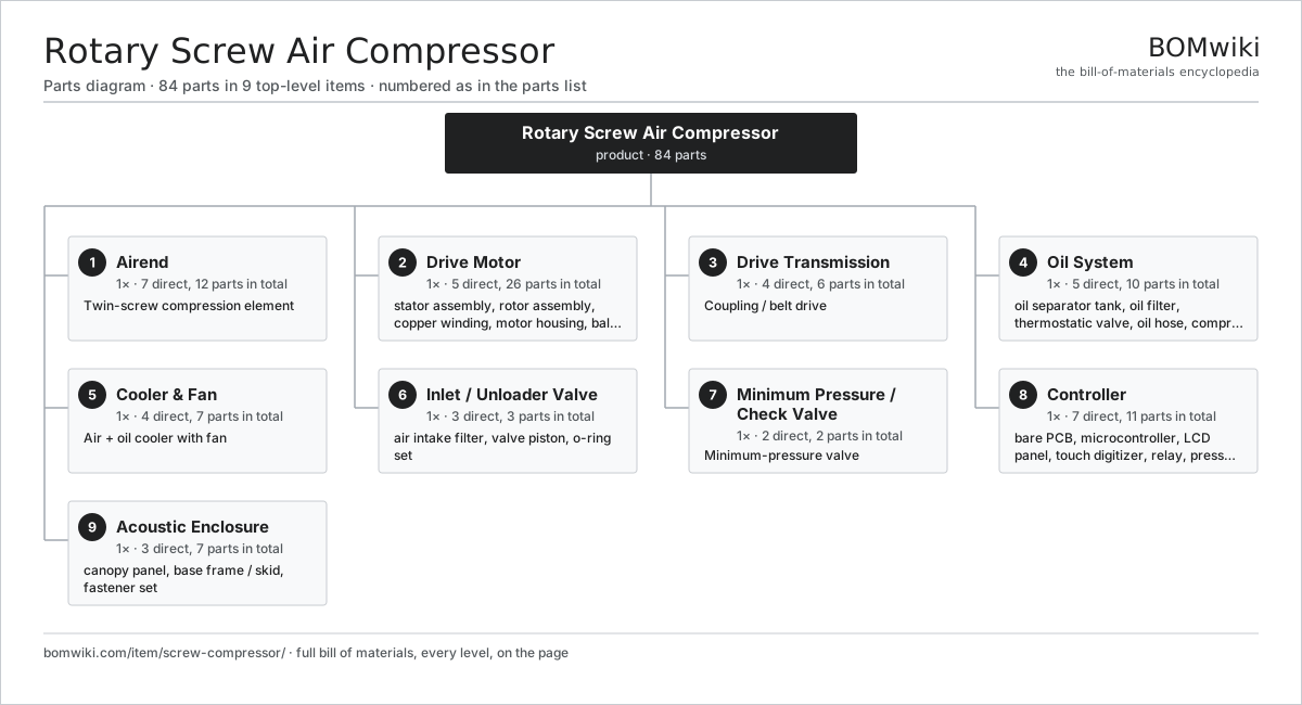
| # | Part | Qty | What it does |
|---|---|---|---|
| 1 | Airend 7 parts | 1× | Twin-screw compression element |
| 2 | Drive Motor 5 parts | 1× | TEFC induction motor driving the airend. |
| 3 | Drive Transmission 4 parts | 1× | Coupling / belt drive |
| 4 | Oil System 5 parts | 1× | Separates, cools, filters and meters the injection oil. |
| 5 | Cooler & Fan 4 parts | 1× | Air + oil cooler with fan |
| 6 | Inlet / Unloader Valve 3 parts | 1× | Throttles intake air and unloads the airend on idle. |
| 7 | Minimum Pressure / Check Valve 2 parts | 1× | Minimum-pressure valve |
| 8 | Controller 7 parts | 1× | Microcontroller load/unload and protection controller with a touchscreen. |
| 9 | Acoustic Enclosure 3 parts | 1× |
3D model
No 3D model yet. Have a CAD file of this? Add a 3D model. STL renders right on this page; STEP, FreeCAD, and OpenSCAD sources are welcome too (openly licensed, like all 3D models on BOMwiki).
Build & assembly graph
expand / collapse · shared sub-assemblies converge · links to related products · est. labourTap an assembly to expand/collapse · tap a part to open it · use “Open page” for any node · drag to pan, scroll to zoom.
Bill of materials for Rotary Screw Air Compressor
9 top-level lines · 62 rows shown · 84 parts total · indented to 3 levels| # | Item / sub-assembly | Part no. | Qty/assy | Ext. qty | Parts | Type |
|---|---|---|---|---|---|---|
| 1 | Airend 7 parts | screw-compressor-airend | 1× | 1 | 12 | assembly |
| 1.1 | Male Rotor | screw-compressor-male-rotor | 1× | 1 | · | part |
| 1.2 | Female Rotor | screw-compressor-female-rotor | 1× | 1 | · | part |
| 1.3 | Airend Housing | screw-compressor-airend-housing | 1× | 1 | · | part |
| 1.4 | Ball Bearing | ball-bearing | 4× | 4 | · | part |
| 1.5 | Thrust Bearing | screw-compressor-thrust-bearing | 2× | 2 | · | part |
| 1.6 | Oil Seal | oil-seal | 2× | 2 | · | part |
| 1.7 | O-Ring Set | oring-set | 1× | 1 | · | part |
| 2 | Drive Motor 5 parts | screw-compressor-drive-motor | 1× | 1 | 26 | assembly |
| 2.1 | Stator Assembly 3 parts | stator-assembly | 1× | 1 | 3 | assembly |
| 2.1.1 | Stator Core (laminations) | stator-core | 1× | 1 | · | part |
| 2.1.2 | Copper Winding | copper-winding | 1× | 1 | · | part |
| 2.1.3 | Slot Insulation | stator-insulation | 1× | 1 | · | part |
| 2.2 | Rotor Assembly 4 parts | rotor-assembly | 1× | 1 | 19 | assembly |
| 2.2.1 | Rotor Shaft | rotor-shaft | 1× | 1 | · | part |
| 2.2.2 | Rotor Core | rotor-core | 1× | 1 | · | part |
| 2.2.3 | Neodymium Magnet | neodymium-magnet | 16× | 16 | · | part |
| 2.2.4 | Ball Bearing | ball-bearing | 1× | 1 | · | part |
| 2.3 | Copper Winding | copper-winding | 1× | 1 | · | part |
| 2.4 | Motor Housing | motor-housing | 1× | 1 | · | part |
| 2.5 | Ball Bearing | ball-bearing | 2× | 2 | · | part |
| 3 | Drive Transmission 4 parts | screw-compressor-drive | 1× | 1 | 6 | assembly |
| 3.1 | Drive Belt | drive-belt | 2× | 2 | · | part |
| 3.2 | Drive Pulley | screw-compressor-pulley | 2× | 2 | · | part |
| 3.3 | Drive Coupling | screw-compressor-coupling | 1× | 1 | · | part |
| 3.4 | Belt Tensioner | screw-compressor-belt-tensioner | 1× | 1 | · | part |
| 4 | Oil System 5 parts | screw-compressor-oil-system | 1× | 1 | 10 | assembly |
| 4.1 | Oil Separator Tank 3 parts | screw-compressor-oil-separator | 1× | 1 | 3 | assembly |
| 4.1.1 | Separator Element | screw-compressor-separator-element | 1× | 1 | · | part |
| 4.1.2 | Scavenge Line | screw-compressor-scavenge-line | 1× | 1 | · | part |
| 4.1.3 | O-Ring Set | oring-set | 1× | 1 | · | part |
| 4.2 | Oil Filter | screw-compressor-oil-filter | 1× | 1 | · | part |
| 4.3 | Thermostatic Valve | screw-compressor-thermostatic-valve | 1× | 1 | · | part |
| 4.4 | Oil Hose | screw-compressor-oil-hose | 4× | 4 | · | part |
| 4.5 | Compressor Oil | screw-compressor-compressor-oil | 1× | 1 | · | part |
| 5 | Cooler & Fan 4 parts | screw-compressor-air-cooling | 1× | 1 | 7 | assembly |
| 5.1 | Air Aftercooler | screw-compressor-aftercooler | 1× | 1 | · | part |
| 5.2 | Oil Cooler | screw-compressor-oil-cooler | 1× | 1 | · | part |
| 5.3 | Cooling Fan 3 parts | screw-compressor-cooling-fan | 1× | 1 | 4 | assembly |
| 5.3.1 | Blower Motor | blower-motor | 1× | 1 | · | part |
| 5.3.2 | Fan Impeller | screw-compressor-fan-blade | 1× | 1 | · | part |
| 5.3.3 | Ball Bearing | ball-bearing | 2× | 2 | · | part |
| 5.4 | Moisture Separator | screw-compressor-moisture-separator | 1× | 1 | · | part |
| 6 | Inlet / Unloader Valve 3 parts | screw-compressor-inlet-valve | 1× | 1 | 3 | assembly |
| 6.1 | Air Intake Filter | screw-compressor-air-filter | 1× | 1 | · | part |
| 6.2 | Valve Piston | screw-compressor-valve-piston | 1× | 1 | · | part |
| 6.3 | O-Ring Set | oring-set | 1× | 1 | · | part |
| 7 | Minimum Pressure / Check Valve 2 parts | screw-compressor-mpv | 1× | 1 | 2 | assembly |
| 7.1 | Check Poppet & Spring | screw-compressor-mpv-poppet | 1× | 1 | · | part |
| 7.2 | O-Ring Set | oring-set | 1× | 1 | · | part |
| 8 | Controller 7 parts | screw-compressor-controller | 1× | 1 | 11 | assembly |
| 8.1 | Bare PCB | pcb-bare | 1× | 1 | · | part |
| 8.2 | Microcontroller | mcu | 1× | 1 | · | part |
| 8.3 | LCD Panel | lcd-panel | 1× | 1 | · | part |
| 8.4 | Touch Digitizer | touch-digitizer | 1× | 1 | · | part |
| 8.5 | Relay | relay | 4× | 4 | · | part |
| 8.6 | Pressure Transducer | screw-compressor-pressure-transducer | 1× | 1 | · | part |
| 8.7 | Temperature Sensor | screw-compressor-temp-sensor | 2× | 2 | · | part |
| 9 | Acoustic Enclosure 3 parts | screw-compressor-enclosure | 1× | 1 | 7 | assembly |
| 9.1 | Canopy Panel | screw-compressor-canopy-panel | 5× | 5 | · | part |
| 9.2 | Base Frame / Skid | screw-compressor-base-frame | 1× | 1 | · | part |
| 9.3 | Fastener Set | fastener-set | 1× | 1 | · | part |
Something wrong in this list? Report a problem with this BOM.
Used in 1 assembly
Related products
same domain, ranked by shared parts Centrifugal Compressor
338 parts · shares 6 with this page
 Hydraulic Power Unit
91 parts · shares 4 with this page
Hydraulic Test Bench
77 parts · shares 4 with this page
 Radial Spillway Gate
264 parts · shares 6 with this page
 High-Pressure Plunger Pump
115 parts · shares 3 with this page
 Irrigation Pump Station
1,881 parts · shares 5 with this page
Sourcing: possible vendors
Browse the supplier directory → Prices, MOQ, and lead times are algorithmic estimates, not quotes, and not claims about these companies. Company mappings are curated by keyword; est. price band $50–$50k. How estimates work| Vendor | HQ | Specialty | MOQ | Lead time |
|---|---|---|---|---|
|
🇩🇰Grundfos
grundfos.com ↗
|
Bjerringbro, DK | Pumps | 200 units | 6–12 wks |
|
🇺🇸Xylem
xylem.com ↗
|
Washington, US | Water technology | 200 units | 6–12 wks |
| flowserve.com ↗ | Irving, US | Pumps & valves | 200 units | 6–12 wks |
|
🇩🇪KSB
ksb.com ↗
|
Frankenthal, DE | Pumps & valves | 200 units | 6–12 wks |
| parker.com ↗ | Cleveland, US | Motion & fluid control | 200 units | 6–12 wks |
375-word article