Hydraulic Cylinder
ProductOverview
A hydraulic cylinder is a linear actuator that converts pressurized hydraulic fluid energy into controlled mechanical motion. It is the most widespread output device in fluid power systems, found in excavators, presses, airframes, and industrial machinery. The cylinder moves a piston inside a steel barrel over a specified stroke, with force output determined by pressure and bore area (F = P × A). Return-path flow is routed through tank via a return line, allowing bidirectional control via a proportional or directional valve.
How it works
Pressurized fluid enters port A, pushing the piston rod outward against external load. The rod displacement (area difference between piston and rod) forces return fluid back through port B to tank. Reversal is achieved by switching inlet/return roles. Speed is governed by flow rate through the valve spool; force is proportional to system pressure. Cushion valves at both ends restrict flow near stroke end, absorbing kinetic energy and preventing shock.
Design elements
The Barrel is a seamless or welded tube rated for full working pressure with safety factor 4:1. Internal surface hardness (1200 HV minimum) resists wear from Seal Kit. The Piston Assembly has dynamic seals (nitrile O-rings for mineral oil, Viton for synthetics) and supports the rod via a bronze or roller Ball Bearing in the Gland Assembly.
The Rod is hard-chromed (0.02–0.05 mm) to prevent corrosion and seal damage. Rod buckling is prevented by limit on unsupported length (L/D < 10); long-stroke cylinders use intermediate rod guides. The Cushion orifice is field-adjustable to match load inertia and prevent cavitation.
Maintenance and reliability
Seal life typically reaches 1000–3000 operating hours before leakage exceeds 10 drops/min. Cylinder rod must be wiped on retraction to prevent contamination; a felt wipers in the gland capture external dust. Fluid cleanliness to ISO 18/16/13 is essential, particle ingress degrades seals and causes stick-slip (jerky motion). Annual inspection includes visual rod corrosion check and pressure-drop testing of seals.
Standards and variants
ISO 1219-1 defines circuit symbols and Port Adapter Set SAE and ISO flange dimensions. Common rod shapes are single-rod (rod only on piston end, asymmetric area, used for pulling) and double-rod (rod both ends, symmetric force). Telescoping cylinders nest multiple stages for long stroke in compact envelope, at the cost of seal count and weight. Rodless cylinders use external profiles and magnetically-coupled piston; used in conveyors and machinery where rod collision is hazard.
Hydraulic Cylinder parts and their functions
8 top-level parts · 17 parts in total · full bill of materials below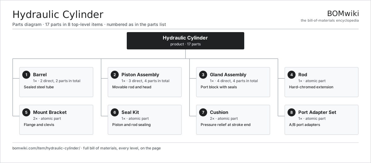
| # | Part | Qty | What it does |
|---|---|---|---|
| 1 | Barrel 2 parts | 1× | Sealed steel tube |
| 2 | Piston Assembly 3 parts | 1× | Movable rod and head |
| 3 | Gland Assembly 4 parts | 1× | Port block with seals |
| 4 | Rod | 1× | Hard-chromed extension |
| 5 | Mount Bracket | 2× | Flange and clevis |
| 6 | Seal Kit | 1× | Piston and rod sealing |
| 7 | Cushion | 2× | Pressure relief at stroke end |
| 8 | Port Adapter Set | 1× | A/B port adapters |
3D model
No 3D model yet. Have a CAD file of this? Add a 3D model. STL renders right on this page; STEP, FreeCAD, and OpenSCAD sources are welcome too (openly licensed, like all 3D models on BOMwiki).
Build & assembly graph
expand / collapse · shared sub-assemblies converge · links to related products · est. labourTap an assembly to expand/collapse · tap a part to open it · use “Open page” for any node · drag to pan, scroll to zoom.
Bill of materials for Hydraulic Cylinder
8 top-level lines · 17 rows shown · 17 parts total · indented to 3 levels| # | Item / sub-assembly | Part no. | Qty/assy | Ext. qty | Parts | Type |
|---|---|---|---|---|---|---|
| 1 | Barrel 2 parts | hydraulic-cylinder-barrel | 1× | 1 | 2 | assembly |
| 1.1 | Sheet Metal Panel | sheet-panel | 1× | 1 | · | part |
| 1.2 | Fastener Set | fastener-set | 1× | 1 | · | part |
| 2 | Piston Assembly 3 parts | hydraulic-cylinder-piston | 1× | 1 | 4 | assembly |
| 2.1 | Piston Head | hydraulic-cylinder-piston-head | 1× | 1 | · | part |
| 2.2 | O-Ring Set | oring-set | 2× | 2 | · | part |
| 2.3 | Fastener Set | fastener-set | 1× | 1 | · | part |
| 3 | Gland Assembly 4 parts | hydraulic-cylinder-gland | 1× | 1 | 4 | assembly |
| 3.1 | Gland Body | hydraulic-cylinder-gland-body | 1× | 1 | · | part |
| 3.2 | Oil Seal | oil-seal | 1× | 1 | · | part |
| 3.3 | Ball Bearing | ball-bearing | 1× | 1 | · | part |
| 3.4 | Pressure Sensor | pressure-sensor | 1× | 1 | · | part |
| 4 | Rod | hydraulic-cylinder-rod | 1× | 1 | · | part |
| 5 | Mount Bracket | hydraulic-cylinder-mounting | 2× | 2 | · | part |
| 6 | Seal Kit | hydraulic-cylinder-seals | 1× | 1 | · | part |
| 7 | Cushion | hydraulic-cylinder-cushioning | 2× | 2 | · | part |
| 8 | Port Adapter Set | hydraulic-cylinder-ports | 1× | 1 | · | part |
Something wrong in this list? Report a problem with this BOM.
Used in 1 assembly
Related products
same domain, ranked by shared parts Irrigation Pump Station
1,881 parts · shares 3 with this page
 Boiler Feedwater Pump
169 parts · shares 2 with this page
 Centrifugal Compressor
338 parts · shares 2 with this page
 High-Pressure Plunger Pump
115 parts · shares 2 with this page
 Hydraulic Power Unit
91 parts · shares 2 with this page
 Liquid-Ring Vacuum Pump
60 parts · shares 2 with this page
Sourcing: possible vendors
Browse the supplier directory → Prices, MOQ, and lead times are algorithmic estimates, not quotes, and not claims about these companies. Company mappings are curated by keyword; est. price band $50–$50k. How estimates work| Vendor | HQ | Specialty | MOQ | Lead time |
|---|---|---|---|---|
|
🇩🇰Grundfos
grundfos.com ↗
|
Bjerringbro, DK | Pumps | 200 units | 6–12 wks |
|
🇺🇸Xylem
xylem.com ↗
|
Washington, US | Water technology | 200 units | 6–12 wks |
| flowserve.com ↗ | Irving, US | Pumps & valves | 200 units | 6–12 wks |
|
🇩🇪KSB
ksb.com ↗
|
Frankenthal, DE | Pumps & valves | 200 units | 6–12 wks |
| parker.com ↗ | Cleveland, US | Motion & fluid control | 200 units | 6–12 wks |
422-word article