Centrifugal Pump
ProductOverview
A centrifugal pump moves liquid by accelerating it radially outward with a rotating impeller, converting the imparted kinetic energy into pressure in a surrounding volute. This close-coupled end-suction model boosts and circulates water for building services, pressure systems, and process duties. The impeller mounts directly to the motor shaft line, so the package is compact and field alignment is limited to the flexible coupling.
The pump divides into the hydraulic Wet End, the Bearing Frame that carries shaft loads, the drive Electric Motor, and electronic control through the Variable Frequency Drive and Pressure Sensor, all bolted to a Baseplate.
How it works
Liquid enters axially through the suction flange of the Wet End and reaches the eye of the closed impeller. The shrouded impeller, keyed to the Pump Shaft and locked by its nut, flings the liquid outward; renewable wear rings hold tight running clearance to limit internal recirculation. The spiral volute casing decelerates the high-velocity flow, recovering it as discharge pressure at the tangential outlet. A balanced single mechanical seal, a carbon rotating face running against a silicon-carbide seat, spring-loaded, seals the shaft where it leaves the casing.
The Bearing Frame supports the shaft on radial and thrust ball bearings in an oil-retaining cast bracket, with oil seals keeping lubricant in and pumped liquid out. Torque comes from the Electric Motor, a TEFC induction motor cooled by a shaft-mounted fan and joined through a Flexible Coupling.
Speed and protection are handled by the Variable Frequency Drive, whose IGBT inverter varies motor frequency to match demand; the Pressure Sensor closes the loop on discharge pressure while a pressure switch guards against dry-running.
Centrifugal Pump parts and their functions
10 top-level parts · 66 parts in total · full bill of materials below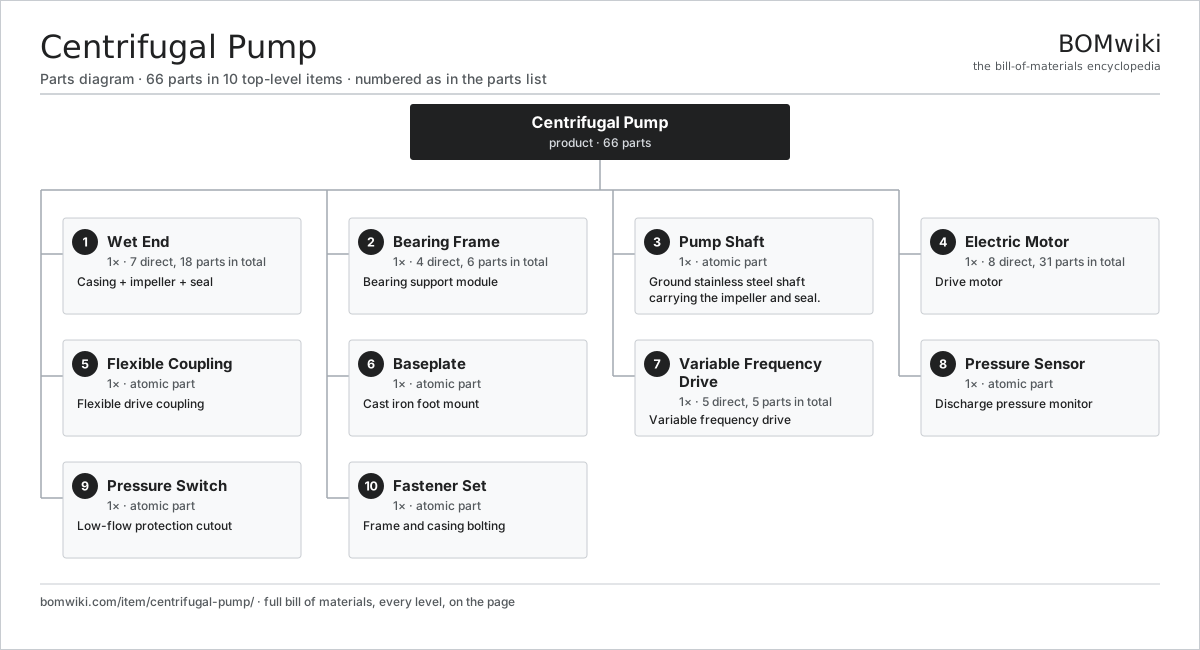
| # | Part | Qty | What it does |
|---|---|---|---|
| 1 | Wet End 7 parts | 1× | Casing + impeller + seal |
| 2 | Bearing Frame 4 parts | 1× | Bearing support module |
| 3 | Pump Shaft | 1× | Ground stainless steel shaft carrying the impeller and seal. |
| 4 | Electric Motor 8 parts | 1× | Drive motor |
| 5 | Flexible Coupling | 1× | Flexible drive coupling |
| 6 | Baseplate | 1× | Cast iron foot mount |
| 7 | Variable Frequency Drive 5 parts | 1× | Variable frequency drive |
| 8 | Pressure Sensor | 1× | Discharge pressure monitor |
| 9 | Pressure Switch | 1× | Low-flow protection cutout |
| 10 | Fastener Set | 1× | Frame and casing bolting |
3D model
No 3D model yet. Have a CAD file of this? Add a 3D model. STL renders right on this page; STEP, FreeCAD, and OpenSCAD sources are welcome too (openly licensed, like all 3D models on BOMwiki).
Build & assembly graph
expand / collapse · shared sub-assemblies converge · links to related products · est. labourTap an assembly to expand/collapse · tap a part to open it · use “Open page” for any node · drag to pan, scroll to zoom.
Bill of materials for Centrifugal Pump
10 top-level lines · 56 rows shown · 66 parts total · indented to 3 levels| # | Item / sub-assembly | Part no. | Qty/assy | Ext. qty | Parts | Type |
|---|---|---|---|---|---|---|
| 1 | Wet End 7 parts | centrifugal-pump-wet-end | 1× | 1 | 18 | assembly |
| 1.1 | Volute Casing 4 parts | centrifugal-pump-casing | 1× | 1 | 4 | assembly |
| 1.1.1 | Volute Body Casting | centrifugal-pump-volute-body | 1× | 1 | · | part |
| 1.1.2 | Suction Flange | centrifugal-pump-suction-flange | 1× | 1 | · | part |
| 1.1.3 | Discharge Flange | centrifugal-pump-discharge-flange | 1× | 1 | · | part |
| 1.1.4 | Casing Wear Ring | centrifugal-pump-wear-ring | 1× | 1 | · | part |
| 1.2 | Closed Impeller 4 parts | centrifugal-pump-impeller | 1× | 1 | 5 | assembly |
| 1.2.1 | Impeller Casting | centrifugal-pump-impeller-body | 1× | 1 | · | part |
| 1.2.2 | Impeller Wear Ring | centrifugal-pump-impeller-wear-ring | 2× | 2 | · | part |
| 1.2.3 | Impeller Nut | centrifugal-pump-impeller-nut | 1× | 1 | · | part |
| 1.2.4 | Impeller Drive Key | centrifugal-pump-impeller-key | 1× | 1 | · | part |
| 1.3 | Mechanical Seal 4 parts | centrifugal-pump-mechanical-seal | 1× | 1 | 4 | assembly |
| 1.3.1 | Rotating Seal Face | centrifugal-pump-seal-rotating-face | 1× | 1 | · | part |
| 1.3.2 | Stationary Seal Seat | centrifugal-pump-seal-stationary-face | 1× | 1 | · | part |
| 1.3.3 | Seal Loading Spring | centrifugal-pump-seal-spring | 1× | 1 | · | part |
| 1.3.4 | O-Ring Set | oring-set | 1× | 1 | · | part |
| 1.4 | Stuffing Box | centrifugal-pump-stuffing-box | 1× | 1 | · | part |
| 1.5 | O-Ring Set | oring-set | 1× | 1 | · | part |
| 1.6 | Drain / Vent Plug | centrifugal-pump-drain-plug | 2× | 2 | · | part |
| 1.7 | Priming Port | centrifugal-pump-priming-port | 1× | 1 | · | part |
| 2 | Bearing Frame 4 parts | centrifugal-pump-bearing-frame | 1× | 1 | 6 | assembly |
| 2.1 | Frame Housing | centrifugal-pump-frame-housing | 1× | 1 | · | part |
| 2.2 | Ball Bearing | ball-bearing | 2× | 2 | · | part |
| 2.3 | Oil Seal | oil-seal | 2× | 2 | · | part |
| 2.4 | Bearing End Cover | centrifugal-pump-bearing-cover | 1× | 1 | · | part |
| 3 | Pump Shaft | centrifugal-pump-shaft | 1× | 1 | · | part |
| 4 | Electric Motor 8 parts | centrifugal-pump-motor | 1× | 1 | 31 | assembly |
| 4.1 | Stator Assembly 3 parts | stator-assembly | 1× | 1 | 3 | assembly |
| 4.1.1 | Stator Core (laminations) | stator-core | 1× | 1 | · | part |
| 4.1.2 | Copper Winding | copper-winding | 1× | 1 | · | part |
| 4.1.3 | Slot Insulation | stator-insulation | 1× | 1 | · | part |
| 4.2 | Rotor Assembly 4 parts | rotor-assembly | 1× | 1 | 19 | assembly |
| 4.2.1 | Rotor Shaft | rotor-shaft | 1× | 1 | · | part |
| 4.2.2 | Rotor Core | rotor-core | 1× | 1 | · | part |
| 4.2.3 | Neodymium Magnet | neodymium-magnet | 16× | 16 | · | part |
| 4.2.4 | Ball Bearing | ball-bearing | 1× | 1 | · | part |
| 4.3 | Copper Winding | copper-winding | 1× | 1 | · | part |
| 4.4 | Motor Housing | motor-housing | 1× | 1 | · | part |
| 4.5 | Ball Bearing | ball-bearing | 2× | 2 | · | part |
| 4.6 | Terminal Box 3 parts | centrifugal-pump-terminal-box | 1× | 1 | 3 | assembly |
| 4.6.1 | Terminal Block | centrifugal-pump-terminal-block | 1× | 1 | · | part |
| 4.6.2 | Wire Bundle | wire-bundle | 1× | 1 | · | part |
| 4.6.3 | Connector | connector | 1× | 1 | · | part |
| 4.7 | Cooling Fan | centrifugal-pump-cooling-fan | 1× | 1 | · | part |
| 4.8 | Fan Cover | centrifugal-pump-fan-cover | 1× | 1 | · | part |
| 5 | Flexible Coupling | centrifugal-pump-coupling | 1× | 1 | · | part |
| 6 | Baseplate | centrifugal-pump-baseplate | 1× | 1 | · | part |
| 7 | Variable Frequency Drive 5 parts | centrifugal-pump-vfd | 1× | 1 | 5 | assembly |
| 7.1 | Bare PCB | pcb-bare | 1× | 1 | · | part |
| 7.2 | IGBT Power Module | igbt-module | 1× | 1 | · | part |
| 7.3 | Microcontroller | mcu | 1× | 1 | · | part |
| 7.4 | VFD Enclosure | centrifugal-pump-vfd-enclosure | 1× | 1 | · | part |
| 7.5 | Wire Bundle | wire-bundle | 1× | 1 | · | part |
| 8 | Pressure Sensor | centrifugal-pump-pressure-sensor | 1× | 1 | · | part |
| 9 | Pressure Switch | pressure-switch | 1× | 1 | · | part |
| 10 | Fastener Set | fastener-set | 1× | 1 | · | part |
Something wrong in this list? Report a problem with this BOM.
Related products
same domain, ranked by shared parts Air Compressor
97 parts · shares 7 with this page
 Submersible Pump
84 parts · shares 7 with this page
 Peristaltic Pump
59 parts · shares 6 with this page
 Irrigation Pump Station
1,881 parts · shares 5 with this page
Mine Dewatering Pump
259 parts · shares 5 with this page
 Ball Valve
61 parts · shares 5 with this page
Sourcing: possible vendors
Browse the supplier directory → Prices, MOQ, and lead times are algorithmic estimates, not quotes, and not claims about these companies. Company mappings are curated by keyword; est. price band $50–$50k. How estimates work| Vendor | HQ | Specialty | MOQ | Lead time |
|---|---|---|---|---|
|
🇩🇰Grundfos
grundfos.com ↗
|
Bjerringbro, DK | Pumps | 200 units | 6–12 wks |
|
🇺🇸Xylem
xylem.com ↗
|
Washington, US | Water technology | 200 units | 6–12 wks |
| flowserve.com ↗ | Irving, US | Pumps & valves | 200 units | 6–12 wks |
|
🇩🇪KSB
ksb.com ↗
|
Frankenthal, DE | Pumps & valves | 200 units | 6–12 wks |
| parker.com ↗ | Cleveland, US | Motion & fluid control | 200 units | 6–12 wks |
299-word article