Boiler Feedwater Pump
ProductOverview
A boiler feedwater pump raises condensate and makeup water from the deaerator storage tank to the pressure needed to push it through the economiser and into the boiler drum or, in once-through units, straight into the furnace waterwalls. It is one of the largest auxiliary loads in a thermal power station and runs continuously whenever the unit is generating. Because the discharge pressure has to exceed boiler drum pressure plus the static lift, friction losses and a control margin, a feed pump for a large utility boiler develops several thousand metres of head, which is why it is built as a multistage machine rather than a single-stage volute pump.
Most large feed pumps use a Barrel Casing Assembly design, classified as type BB5 in API 610. A single forged outer barrel takes the full discharge pressure, and a removable Inner Stack (Cartridge) carrying the diffusers and stage casings slides in as a cartridge. This arrangement keeps a heavy pressure joint away from the radial split, so the casing stays tight through fast thermal transients. Smaller feed pumps are built as ring-section (segmental) machines, where individual stage casings are clamped together by long Stack Tie Bolt tie bolts.
Rotating element
The heart of the pump is the Rotating Element. A forged Pump Shaft carries a series of closed impellers in line. The First-Stage Impeller is designed for low NPSH, sometimes as a double-suction eye or with an inducer ahead of it, because the suction stage sees the worst cavitation conditions. The following Series Impeller stages each add roughly the same head increment, and flow passes from one to the next through a stationary Diffuser and Return Channel Vane that turn the discharge of one stage back into the eye of the next.
Clearances between rotating and stationary parts are set by renewable wear rings. Each impeller carries a Impeller Wear Ring running against a Stationary Wear Ring pressed into the casing. These rings throttle the leakage from impeller discharge back to suction. As they wear, internal recirculation rises and efficiency falls, so they are made of hardened 13Cr stainless and treated as consumable parts at overhaul. A Shaft Sleeve protects the shaft where it passes through each seal.
Axial thrust and balance device
Stacking impellers in one direction generates a large axial thrust toward the suction end. A Balance Drum handles most of it. High-pressure water from the last stage acts on the back of the drum and leaks across the close clearance of a stationary Balance Drum Bush into a low-pressure chamber that is piped back through the Balance Leak-off Line to the suction or the deaerator. The pressure difference across the drum produces a force opposing the impeller thrust. The small residual thrust, and any reverse thrust during transients, is carried by a Tilting-Pad Thrust Bearing of the tilting-pad type. Radial load is taken by white-metal Journal Bearing units, fed from the Lube Oil System through an Oil Cooler and a duplex Duplex Oil Filter.
Shaft sealing
Each shaft penetration uses a Cartridge Mechanical Seal, a balanced cartridge mechanical seal built to API 682. Feedwater is hot and close to its saturation temperature, so it will flash if it drops below seal-chamber pressure. The seal flush is cooled in a Seal Flush Cooler following an API Plan 23 arrangement, which recirculates a small flow through a heat exchanger to hold the faces below the flash point. A Throttle Bushing downstream of the seal limits leakage to the atmospheric side. Older designs used floating-ring or labyrinth breakdown seals, but cartridge seals are now standard because they cut leakage and simplify maintenance.
NPSH, cavitation and booster pumps
Feedwater leaves the deaerator at saturation temperature, so the available NPSH is small and is set mainly by the static height of the storage tank above the pump. If the suction pressure margin is lost, water flashes at the impeller eye, the resulting bubbles collapse downstream and erode the metal, and head drops away. Two measures protect against this. The deaerator tank is mounted high in the boiler house to give static head, and a low-speed Pressure Sensor-monitored booster pump is installed ahead of the main pump to raise suction pressure before the first stage. The booster runs at a fraction of main-pump speed, often off the same shaft through a gear, and gives the main pump the NPSH it needs at full load.
Minimum flow and control
A feed pump must never run for long at very low flow. At low flow the power that does not go into the water turns into heat, the feedwater warms toward saturation in the casing and flashes, and the rotor can suffer from recirculation-driven vibration. The Minimum-Flow System guards against this. An automatic Automatic Recirculation Valve opens a recirculation path back to the deaerator whenever forward flow falls below the minimum continuous safe value, and a Breakdown Orifice breaks down the bypass pressure in stages so the flow does not flash. Output is matched to boiler demand either by variable-speed drive, by a hydraulic coupling, or by a feed regulating valve on the discharge.
Materials and common failures
Casings are forged low-alloy steel such as 2.25Cr-1Mo, while impellers, diffusers and wear rings are martensitic or precipitation-hardened stainless for erosion and cavitation resistance. The most common problems are wear-ring and balance-drum clearance opening up, which shows as lost head and rising leak-off flow; cavitation damage on the first-stage impeller when NPSH margin is squeezed; seal failures from loss of flush cooling; and rotor instability if the pump is run below minimum flow. Condition monitoring through the Vibration Probe set, the Thrust Position Probe and bearing Bearing RTD sensors, wired to an API 670 protection rack, catches most of these before they force an outage.
Boiler Feedwater Pump parts and their functions
10 top-level parts · 169 parts in total · full bill of materials below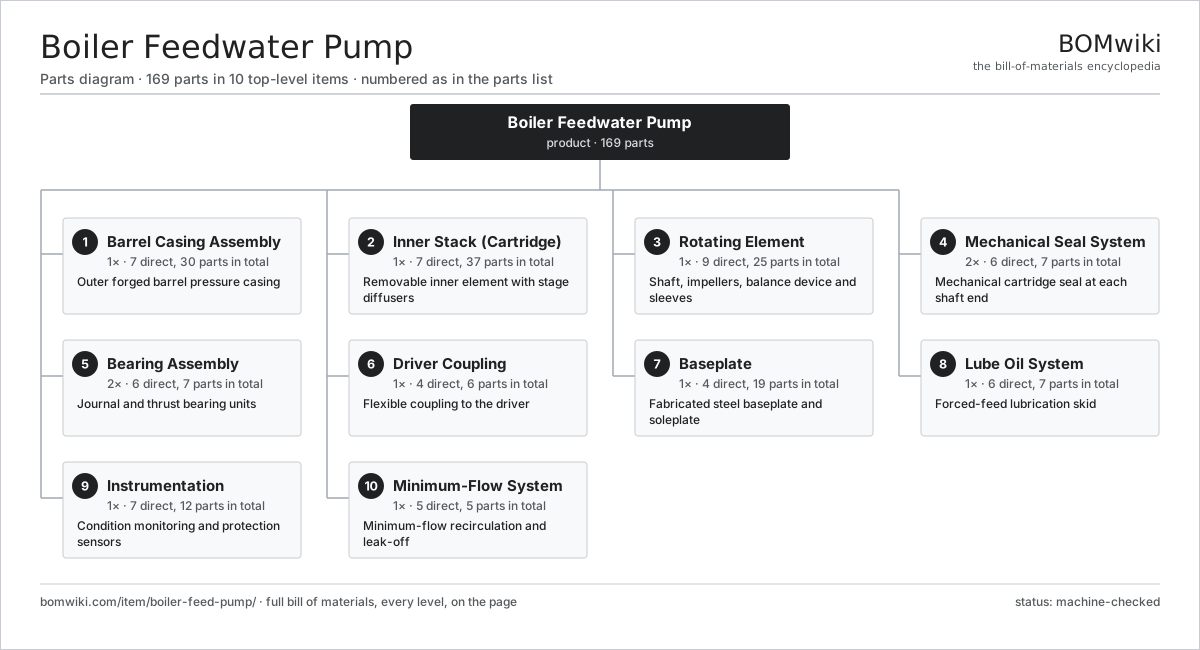
| # | Part | Qty | What it does |
|---|---|---|---|
| 1 | Barrel Casing Assembly 7 parts | 1× | Outer forged barrel pressure casing |
| 2 | Inner Stack (Cartridge) 7 parts | 1× | Removable inner element with stage diffusers |
| 3 | Rotating Element 9 parts | 1× | Shaft, impellers, balance device and sleeves |
| 4 | Mechanical Seal System 6 parts | 2× | Mechanical cartridge seal at each shaft end |
| 5 | Bearing Assembly 6 parts | 2× | Journal and thrust bearing units |
| 6 | Driver Coupling 4 parts | 1× | Flexible coupling to the driver |
| 7 | Baseplate 4 parts | 1× | Fabricated steel baseplate and soleplate |
| 8 | Lube Oil System 6 parts | 1× | Forced-feed lubrication skid |
| 9 | Instrumentation 7 parts | 1× | Condition monitoring and protection sensors |
| 10 | Minimum-Flow System 5 parts | 1× | Minimum-flow recirculation and leak-off |
3D model
No 3D model yet. Have a CAD file of this? Add a 3D model. STL renders right on this page; STEP, FreeCAD, and OpenSCAD sources are welcome too (openly licensed, like all 3D models on BOMwiki).
Build & assembly graph
expand / collapse · shared sub-assemblies converge · links to related products · est. labourTap an assembly to expand/collapse · tap a part to open it · use “Open page” for any node · drag to pan, scroll to zoom.
Bill of materials for Boiler Feedwater Pump
10 top-level lines · 71 rows shown · 169 parts total · indented to 3 levels| # | Item / sub-assembly | Part no. | Qty/assy | Ext. qty | Parts | Type |
|---|---|---|---|---|---|---|
| 1 | Barrel Casing Assembly 7 parts | boiler-feed-pump-barrel-casing | 1× | 1 | 30 | assembly |
| 1.1 | Barrel Body Forging | boiler-feed-pump-barrel-body | 1× | 1 | · | part |
| 1.2 | Discharge Cover | boiler-feed-pump-discharge-cover | 1× | 1 | · | part |
| 1.3 | Suction Nozzle | boiler-feed-pump-suction-nozzle | 1× | 1 | · | part |
| 1.4 | Discharge Nozzle | boiler-feed-pump-discharge-nozzle | 1× | 1 | · | part |
| 1.5 | Cover Joint Gasket | boiler-feed-pump-cover-gasket | 1× | 1 | · | part |
| 1.6 | Cover Stud and Nut | boiler-feed-pump-cover-studs | 24× | 24 | · | part |
| 1.7 | Fastener Set | fastener-set | 1× | 1 | · | part |
| 2 | Inner Stack (Cartridge) 7 parts | boiler-feed-pump-inner-stack | 1× | 1 | 37 | assembly |
| 2.1 | Suction Stage Casing | boiler-feed-pump-suction-stage-casing | 1× | 1 | · | part |
| 2.2 | Stage Casing | boiler-feed-pump-stage-casing | 5× | 5 | · | part |
| 2.3 | Diffuser | boiler-feed-pump-diffuser | 6× | 6 | · | part |
| 2.4 | Return Channel Vane | boiler-feed-pump-return-channel | 5× | 5 | · | part |
| 2.5 | Stationary Wear Ring | boiler-feed-pump-stage-casing-wear-ring | 6× | 6 | · | part |
| 2.6 | Stack Tie Bolt | boiler-feed-pump-tie-bolt | 8× | 8 | · | part |
| 2.7 | Inter-stage Gasket | boiler-feed-pump-stage-gasket | 6× | 6 | · | part |
| 3 | Rotating Element 9 parts | boiler-feed-pump-rotating-element | 1× | 1 | 25 | assembly |
| 3.1 | Pump Shaft | boiler-feed-pump-shaft | 1× | 1 | · | part |
| 3.2 | First-Stage Impeller | boiler-feed-pump-impeller-first | 1× | 1 | · | part |
| 3.3 | Series Impeller | boiler-feed-pump-impeller | 5× | 5 | · | part |
| 3.4 | Impeller Wear Ring | boiler-feed-pump-impeller-wear-ring | 6× | 6 | · | part |
| 3.5 | Balance Drum | boiler-feed-pump-balance-drum | 1× | 1 | · | part |
| 3.6 | Balance Drum Bush | boiler-feed-pump-balance-drum-bush | 1× | 1 | · | part |
| 3.7 | Shaft Sleeve | boiler-feed-pump-shaft-sleeve | 2× | 2 | · | part |
| 3.8 | Impeller Drive Key | boiler-feed-pump-impeller-key | 6× | 6 | · | part |
| 3.9 | Shaft Locking Nut | boiler-feed-pump-shaft-nut | 2× | 2 | · | part |
| 4 | Mechanical Seal System 6 parts | boiler-feed-pump-seal-system | 2× | 2 | 7 | assembly |
| 4.1 | Cartridge Mechanical Seal | boiler-feed-pump-seal-cartridge | 1× | 2 | · | part |
| 4.2 | Throttle Bushing | boiler-feed-pump-throttle-bushing | 1× | 2 | · | part |
| 4.3 | Seal Flush Cooler | boiler-feed-pump-seal-flush-cooler | 1× | 2 | · | part |
| 4.4 | Seal Gland Plate | boiler-feed-pump-seal-gland | 1× | 2 | · | part |
| 4.5 | O-Ring Set | oring-set | 2× | 4 | · | part |
| 4.6 | Oil Seal | oil-seal | 1× | 2 | · | part |
| 5 | Bearing Assembly 6 parts | boiler-feed-pump-bearing-assembly | 2× | 2 | 7 | assembly |
| 5.1 | Journal Bearing | boiler-feed-pump-journal-bearing | 1× | 2 | · | part |
| 5.2 | Tilting-Pad Thrust Bearing | boiler-feed-pump-thrust-bearing | 1× | 2 | · | part |
| 5.3 | Bearing Housing | boiler-feed-pump-bearing-housing | 1× | 2 | · | part |
| 5.4 | Ball Bearing | ball-bearing | 1× | 2 | · | part |
| 5.5 | Oil Seal | oil-seal | 2× | 4 | · | part |
| 5.6 | Fastener Set | fastener-set | 1× | 2 | · | part |
| 6 | Driver Coupling 4 parts | boiler-feed-pump-coupling | 1× | 1 | 6 | assembly |
| 6.1 | Coupling Hub | boiler-feed-pump-coupling-hub | 2× | 2 | · | part |
| 6.2 | Coupling Spacer | boiler-feed-pump-coupling-spacer | 1× | 1 | · | part |
| 6.3 | Flexible Disc Pack | boiler-feed-pump-flex-element | 2× | 2 | · | part |
| 6.4 | Fastener Set | fastener-set | 1× | 1 | · | part |
| 7 | Baseplate 4 parts | boiler-feed-pump-baseplate | 1× | 1 | 19 | assembly |
| 7.1 | Base Frame | boiler-feed-pump-base-frame | 1× | 1 | · | part |
| 7.2 | Soleplate | boiler-feed-pump-soleplate | 2× | 2 | · | part |
| 7.3 | Anchor Bolt | boiler-feed-pump-anchor-bolt | 8× | 8 | · | part |
| 7.4 | Jacking Screw | boiler-feed-pump-jacking-screw | 8× | 8 | · | part |
| 8 | Lube Oil System 6 parts | boiler-feed-pump-lube-oil-system | 1× | 1 | 7 | assembly |
| 8.1 | Lube Oil Pump | boiler-feed-pump-oil-pump | 1× | 1 | · | part |
| 8.2 | Oil Cooler | boiler-feed-pump-oil-cooler | 1× | 1 | · | part |
| 8.3 | Duplex Oil Filter | boiler-feed-pump-oil-filter | 2× | 2 | · | part |
| 8.4 | Oil Reservoir | boiler-feed-pump-oil-reservoir | 1× | 1 | · | part |
| 8.5 | Oil Relief Valve | boiler-feed-pump-relief-valve | 1× | 1 | · | part |
| 8.6 | Pressure Sensor | pressure-sensor | 1× | 1 | · | part |
| 9 | Instrumentation 7 parts | boiler-feed-pump-instrumentation | 1× | 1 | 12 | assembly |
| 9.1 | Vibration Probe | boiler-feed-pump-vibration-probe | 2× | 2 | · | part |
| 9.2 | Thrust Position Probe | boiler-feed-pump-thrust-probe | 1× | 1 | · | part |
| 9.3 | Bearing RTD | boiler-feed-pump-bearing-rtd | 4× | 4 | · | part |
| 9.4 | Pressure Sensor | pressure-sensor | 2× | 2 | · | part |
| 9.5 | Speed Pickup | boiler-feed-pump-tacho | 1× | 1 | · | part |
| 9.6 | Connector | connector | 1× | 1 | · | part |
| 9.7 | Wire Bundle | wire-bundle | 1× | 1 | · | part |
| 10 | Minimum-Flow System 5 parts | boiler-feed-pump-min-flow-system | 1× | 1 | 5 | assembly |
| 10.1 | Automatic Recirculation Valve | boiler-feed-pump-min-flow-valve | 1× | 1 | · | part |
| 10.2 | Balance Leak-off Line | boiler-feed-pump-leak-off-line | 1× | 1 | · | part |
| 10.3 | Breakdown Orifice | boiler-feed-pump-orifice | 1× | 1 | · | part |
| 10.4 | Flow Element | boiler-feed-pump-flow-element | 1× | 1 | · | part |
| 10.5 | Fastener Set | fastener-set | 1× | 1 | · | part |
Related products
same domain, ranked by shared parts Hydraulic Power Unit
91 parts · shares 4 with this page
Hydraulic Power Unit
91 parts · shares 4 with this page
 Irrigation Pump Station
1,881 parts · shares 4 with this page
Mine Dewatering Pump
259 parts · shares 4 with this page
Irrigation Pump Station
1,881 parts · shares 4 with this page
Mine Dewatering Pump
259 parts · shares 4 with this page
 Mainline Pipeline Pump
166 parts · shares 3 with this page
Mainline Pipeline Pump
166 parts · shares 3 with this page
 Metering / Dosing Pump
44 parts · shares 3 with this page
Metering / Dosing Pump
44 parts · shares 3 with this page
 Pneumatic Pinch Valve
33 parts · shares 3 with this page
Pneumatic Pinch Valve
33 parts · shares 3 with this page
Sourcing: possible vendors
Browse the supplier directory → Prices, MOQ, and lead times are algorithmic estimates, not quotes, and not claims about these companies. Company mappings are curated by keyword; est. price band $50–$50k. How estimates work| Vendor | HQ | Specialty | MOQ | Lead time |
|---|---|---|---|---|
|
🇩🇰Grundfos
grundfos.com ↗
|
Bjerringbro, DK | Pumps | 200 units | 6–12 wks |
|
🇺🇸Xylem
xylem.com ↗
|
Washington, US | Water technology | 200 units | 6–12 wks |
| flowserve.com ↗ | Irving, US | Pumps & valves | 200 units | 6–12 wks |
|
🇩🇪KSB
ksb.com ↗
|
Frankenthal, DE | Pumps & valves | 200 units | 6–12 wks |
| parker.com ↗ | Cleveland, US | Motion & fluid control | 200 units | 6–12 wks |
1,059-word article