Condenser Cooling Water Pump
ProductOverview
A condenser cooling water pump moves the large volume of water that carries waste heat away from a steam surface condenser. In a thermal or nuclear power station the condenser rejects the latent heat of the exhaust steam to a cooling water stream, and that stream is supplied by one or more of these pumps. The duty is high flow at low head: a single unit commonly delivers between 10,000 and 100,000 m3/h against a total head of only 8 to 20 m, because the resistance to overcome is mostly the friction of the intake screens, the condenser tube bundle and the discharge culvert, not a tall static lift. The hydraulic design that matches this duty is a mixed-flow or axial-flow stage rather than a radial centrifugal one.
The machine is built as a vertical wet-pit column pump. The hydraulic Pump Bowl Assembly sits submerged in the intake sump, a Column and Discharge Assembly carries the flow up to floor level and encloses the rotating line shaft, and a Discharge Head turns the water out to the cooling main while supporting the motor. Power comes from a Vertical Hollow-Shaft Motor, a vertical hollow-shaft motor that also carries the pump thrust.
Mixed-flow and axial-flow hydraulics
At these flows a radial impeller would be impractically large, so the impeller develops head through a combination of centrifugal and axial action. A mixed-flow Mixed-Flow Impeller discharges water at an angle between radial and axial and suits the upper end of the head range, while a true axial-flow propeller suits the lowest heads and highest flows. The Diffuser Bowl downstream of the impeller straightens the swirl and recovers velocity into pressure. Running clearance between the Impeller Wear Ring and the Bowl Wear Ring sets internal leakage and therefore efficiency; these rings are renewable so the bowl casting itself is not consumed as clearances open with wear.
Specific speed for these pumps is high, which is why the head-flow curve is steep and the power curve rises toward shut-off. Operators avoid running an axial-flow unit near shut-off because the power draw and vibration both peak there.
Line shaft and bearings
The impeller is driven through a Bowl Shaft joined to a stack of Line Shaft Section sections, connected by threaded Line Shaft Coupling sleeves and supported at intervals by a Bearing Spider in the column bore. Most units use water-lubricated Cutless Rubber Bearing elements, fluted rubber bushings that run on a hardened Shaft Journal Sleeve and are flushed by the pumped water itself. Because the bearings depend on water for lubrication, a Pre-Lube Water Tank wets them before the column fills on startup, and a dry start of more than a few seconds will glaze the rubber. Where the water is too dirty for self-lubrication, an enclosed line shaft with injected clean water or grease is used instead, supplied through the Lubrication Tubing.
Seawater corrosion, erosion and biofouling
Coastal stations draw seawater, and that drives the material selection throughout the wetted path. The impeller is cast in Ni-Al bronze and the shaft is duplex stainless or 17-4 PH, both chosen for resistance to chloride pitting and to the erosion of suspended sand. Galvanic pairing is managed carefully so that the more noble stainless components do not accelerate attack on the bronze, and sacrificial anodes are often fitted in the sump. Biofouling is a constant problem: barnacles and mussels colonise the bell, the strainer and the column interior, narrowing flow passages and raising head loss. Many intakes dose chlorine or another biocide upstream, and the Suction Strainer Basket is sized for periodic removal and cleaning.
Intake and sump design
A wet-pit pump is only as good as the sump that feeds it. Uneven approach flow produces surface and subsurface vortices that draw air or swirl into the Suction Bell, which lowers capacity and raises vibration. The sump therefore includes a floor Anti-Vortex Cone under each bell and a back-wall Anti-Swirl Baffle to suppress rotation, with bay widths and submergence set by the Hydraulic Institute HI 9.8 standard. Ahead of the pumps a Trash Rack stops large debris and a screen panel removes the rest. Minimum submergence over the bell must be maintained at all tide and load conditions, which is why a Sump Level Transmitter trips the unit if the sump runs low.
Drivers and thrust
The pump hangs from a vertical hollow-shaft motor. The Head Shaft passes up through the motor hollow shaft and is clamped at the top by an Shaft Adjusting Nut that also sets impeller running clearance. Downward hydraulic thrust from the impeller, plus the weight of the entire rotating column, is carried by the motor Motor Thrust Bearing, commonly a spherical-roller or tilting-pad bearing. A Non-Reverse Ratchet blocks reverse rotation when a stopped pump would otherwise be spun backward by water draining out of the column.
Common failures and monitoring
The recurring failure modes are bearing wear from dirty or aerated water, shaft fatigue at the couplings, impeller and wear-ring erosion in sandy water, and seal leakage at the head where a packed Shaft Sealing box or a cartridge seal controls the small amount of water that escapes along the shaft. Sustained low submergence causes air entrainment that erodes the impeller and unbalances the rotor. Continuous condition monitoring catches these early: a Vibration Sensor on the motor and head, a Bearing RTD on each bearing, and a discharge Pressure Sensor together show when clearances have opened, when a bearing is overheating, or when the unit has drifted off its best efficiency point.
Condenser Cooling Water Pump parts and their functions
8 top-level parts · 117 parts in total · full bill of materials below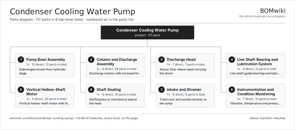
| # | Part | Qty | What it does |
|---|---|---|---|
| 1 | Pump Bowl Assembly 12 parts | 1× | Submerged mixed-flow hydraulic stage |
| 2 | Column and Discharge Assembly 8 parts | 1× | Discharge column with enclosed line shaft |
| 3 | Discharge Head 7 parts | 1× | Above-floor elbow head carrying the driver |
| 4 | Line Shaft Bearing and Lubrication System 6 parts | 1× | Line shaft guide bearings and lubrication |
| 5 | Vertical Hollow-Shaft Motor 9 parts | 1× | Vertical hollow-shaft motor with thrust bearing |
| 6 | Shaft Sealing 6 parts | 1× | Stuffing box or mechanical seal at the head |
| 7 | Intake and Strainer 6 parts | 1× | Trash rack and suction strainer at the sump |
| 8 | Instrumentation and Condition Monitoring 7 parts | 1× | Vibration, temperature and pressure monitoring |
3D model
No 3D model yet. Have a CAD file of this? Add a 3D model. STL renders right on this page; STEP, FreeCAD, and OpenSCAD sources are welcome too (openly licensed, like all 3D models on BOMwiki).
Build & assembly graph
expand / collapse · shared sub-assemblies converge · links to related products · est. labourTap an assembly to expand/collapse · tap a part to open it · use “Open page” for any node · drag to pan, scroll to zoom.
Bill of materials for Condenser Cooling Water Pump
8 top-level lines · 76 rows shown · 117 parts total · indented to 3 levels| # | Item / sub-assembly | Part no. | Qty/assy | Ext. qty | Parts | Type |
|---|---|---|---|---|---|---|
| 1 | Pump Bowl Assembly 12 parts | condenser-cooling-pump-bowl-assembly | 1× | 1 | 13 | assembly |
| 1.1 | Mixed-Flow Impeller | condenser-cooling-pump-impeller | 1× | 1 | · | part |
| 1.2 | Diffuser Bowl | condenser-cooling-pump-bowl-diffuser | 1× | 1 | · | part |
| 1.3 | Suction Bell | condenser-cooling-pump-suction-bell | 1× | 1 | · | part |
| 1.4 | Impeller Wear Ring | condenser-cooling-pump-impeller-wear-ring | 1× | 1 | · | part |
| 1.5 | Bowl Wear Ring | condenser-cooling-pump-bowl-wear-ring | 1× | 1 | · | part |
| 1.6 | Bowl Shaft | condenser-cooling-pump-bowl-shaft | 1× | 1 | · | part |
| 1.7 | Bowl Cutless Bearing | condenser-cooling-pump-bowl-bearing | 2× | 2 | · | part |
| 1.8 | Impeller Locking Collet | condenser-cooling-pump-impeller-lock | 1× | 1 | · | part |
| 1.9 | Sand Collar | condenser-cooling-pump-sand-collar | 1× | 1 | · | part |
| 1.10 | Bell Strainer Cone | condenser-cooling-pump-suction-strainer-cone | 1× | 1 | · | part |
| 1.11 | Fastener Set | fastener-set | 1× | 1 | · | part |
| 1.12 | O-Ring Set | oring-set | 1× | 1 | · | part |
| 2 | Column and Discharge Assembly 8 parts | condenser-cooling-pump-column-assembly | 1× | 1 | 29 | assembly |
| 2.1 | Column Pipe Section | condenser-cooling-pump-column-pipe | 4× | 4 | · | part |
| 2.2 | Line Shaft Section | condenser-cooling-pump-line-shaft | 4× | 4 | · | part |
| 2.3 | Line Shaft Coupling | condenser-cooling-pump-shaft-coupling | 4× | 4 | · | part |
| 2.4 | Bearing Spider | condenser-cooling-pump-bearing-spider | 4× | 4 | · | part |
| 2.5 | Bearing Retainer | condenser-cooling-pump-bearing-retainer | 4× | 4 | · | part |
| 2.6 | Shaft Journal Sleeve | condenser-cooling-pump-shaft-sleeve | 4× | 4 | · | part |
| 2.7 | Column Flange Gasket | condenser-cooling-pump-column-flange-gasket | 4× | 4 | · | part |
| 2.8 | Fastener Set | fastener-set | 1× | 1 | · | part |
| 3 | Discharge Head 7 parts | condenser-cooling-pump-discharge-head | 1× | 1 | 7 | assembly |
| 3.1 | Discharge Elbow | condenser-cooling-pump-head-elbow | 1× | 1 | · | part |
| 3.2 | Sole Plate | condenser-cooling-pump-sole-plate | 1× | 1 | · | part |
| 3.3 | Motor Mounting Stool | condenser-cooling-pump-motor-stool | 1× | 1 | · | part |
| 3.4 | Stuffing Box Housing | condenser-cooling-pump-stuffing-box-housing | 1× | 1 | · | part |
| 3.5 | Discharge Flange | condenser-cooling-pump-discharge-flange | 1× | 1 | · | part |
| 3.6 | Head Shaft | condenser-cooling-pump-head-shaft | 1× | 1 | · | part |
| 3.7 | Fastener Set | fastener-set | 1× | 1 | · | part |
| 4 | Line Shaft Bearing and Lubrication System 6 parts | condenser-cooling-pump-lineshaft-bearing-system | 1× | 1 | 12 | assembly |
| 4.1 | Cutless Rubber Bearing | condenser-cooling-pump-cutless-bearing | 4× | 4 | · | part |
| 4.2 | Pre-Lube Water Tank | condenser-cooling-pump-prelube-tank | 1× | 1 | · | part |
| 4.3 | Pre-Lube Solenoid Valve | condenser-cooling-pump-prelube-solenoid | 1× | 1 | · | part |
| 4.4 | Grease Injector | condenser-cooling-pump-grease-injector | 1× | 1 | · | part |
| 4.5 | Lubrication Tubing | condenser-cooling-pump-lube-tubing | 1× | 1 | · | part |
| 4.6 | Bearing Backing Bushing | condenser-cooling-pump-bearing-bushing | 4× | 4 | · | part |
| 5 | Vertical Hollow-Shaft Motor 9 parts | condenser-cooling-pump-driver | 1× | 1 | 30 | assembly |
| 5.1 | Stator Assembly 3 parts | stator-assembly | 1× | 1 | 3 | assembly |
| 5.1.1 | Stator Core (laminations) | stator-core | 1× | 1 | · | part |
| 5.1.2 | Copper Winding | copper-winding | 1× | 1 | · | part |
| 5.1.3 | Slot Insulation | stator-insulation | 1× | 1 | · | part |
| 5.2 | Rotor Assembly 4 parts | rotor-assembly | 1× | 1 | 19 | assembly |
| 5.2.1 | Rotor Shaft | rotor-shaft | 1× | 1 | · | part |
| 5.2.2 | Rotor Core | rotor-core | 1× | 1 | · | part |
| 5.2.3 | Neodymium Magnet | neodymium-magnet | 16× | 16 | · | part |
| 5.2.4 | Ball Bearing | ball-bearing | 1× | 1 | · | part |
| 5.3 | Motor Hollow Shaft | condenser-cooling-pump-hollow-shaft | 1× | 1 | · | part |
| 5.4 | Motor Thrust Bearing | condenser-cooling-pump-thrust-bearing | 1× | 1 | · | part |
| 5.5 | Motor Guide Bearing | condenser-cooling-pump-motor-guide-bearing | 2× | 2 | · | part |
| 5.6 | Non-Reverse Ratchet | condenser-cooling-pump-nonreverse-ratchet | 1× | 1 | · | part |
| 5.7 | Shaft Adjusting Nut | condenser-cooling-pump-adjusting-nut | 1× | 1 | · | part |
| 5.8 | Motor Cooling Fan | condenser-cooling-pump-motor-fan | 1× | 1 | · | part |
| 5.9 | Motor Terminal Box | condenser-cooling-pump-motor-terminal-box | 1× | 1 | · | part |
| 6 | Shaft Sealing 6 parts | condenser-cooling-pump-shaft-sealing | 1× | 1 | 10 | assembly |
| 6.1 | Packing Ring | condenser-cooling-pump-packing-rings | 5× | 5 | · | part |
| 6.2 | Lantern Ring | condenser-cooling-pump-lantern-ring | 1× | 1 | · | part |
| 6.3 | Gland Follower | condenser-cooling-pump-gland-follower | 1× | 1 | · | part |
| 6.4 | Cartridge Mechanical Seal | condenser-cooling-pump-mechanical-seal | 1× | 1 | · | part |
| 6.5 | Seal Flush Line | condenser-cooling-pump-seal-flush-line | 1× | 1 | · | part |
| 6.6 | O-Ring Set | oring-set | 1× | 1 | · | part |
| 7 | Intake and Strainer 6 parts | condenser-cooling-pump-intake-strainer | 1× | 1 | 6 | assembly |
| 7.1 | Trash Rack | condenser-cooling-pump-trash-rack | 1× | 1 | · | part |
| 7.2 | Suction Strainer Basket | condenser-cooling-pump-suction-strainer-basket | 1× | 1 | · | part |
| 7.3 | Anti-Vortex Cone | condenser-cooling-pump-anti-vortex-cone | 1× | 1 | · | part |
| 7.4 | Anti-Swirl Baffle | condenser-cooling-pump-fillet-baffle | 1× | 1 | · | part |
| 7.5 | Debris Screen Panel | condenser-cooling-pump-debris-screen | 1× | 1 | · | part |
| 7.6 | Fastener Set | fastener-set | 1× | 1 | · | part |
| 8 | Instrumentation and Condition Monitoring 7 parts | condenser-cooling-pump-instrumentation | 1× | 1 | 10 | assembly |
| 8.1 | Vibration Sensor | condenser-cooling-pump-vibration-sensor | 2× | 2 | · | part |
| 8.2 | Bearing RTD | condenser-cooling-pump-bearing-rtd | 3× | 3 | · | part |
| 8.3 | Pressure Sensor | pressure-sensor | 1× | 1 | · | part |
| 8.4 | Sump Level Transmitter | condenser-cooling-pump-level-transmitter | 1× | 1 | · | part |
| 8.5 | Cooling Water Flow Meter | condenser-cooling-pump-flow-meter | 1× | 1 | · | part |
| 8.6 | Instrument Junction Box | condenser-cooling-pump-junction-box | 1× | 1 | · | part |
| 8.7 | Wire Bundle | wire-bundle | 1× | 1 | · | part |
Related products
same domain, ranked by shared parts Boiler Feedwater Pump
169 parts · shares 2 with this page
Boiler Feedwater Pump
169 parts · shares 2 with this page
 Hydraulic Power Unit
91 parts · shares 2 with this page
Hydraulic Power Unit
91 parts · shares 2 with this page
 Irrigation Pump Station
1,881 parts · shares 2 with this page
Irrigation Pump Station
1,881 parts · shares 2 with this page
 Mainline Pipeline Pump
166 parts · shares 2 with this page
Mainline Pipeline Pump
166 parts · shares 2 with this page
 Metering / Dosing Pump
44 parts · shares 2 with this page
Mine Dewatering Pump
259 parts · shares 2 with this page
Metering / Dosing Pump
44 parts · shares 2 with this page
Mine Dewatering Pump
259 parts · shares 2 with this page
Sourcing: possible vendors
Browse the supplier directory → Prices, MOQ, and lead times are algorithmic estimates, not quotes, and not claims about these companies. Company mappings are curated by keyword; est. price band $50–$50k. How estimates work| Vendor | HQ | Specialty | MOQ | Lead time |
|---|---|---|---|---|
|
🇩🇰Grundfos
grundfos.com ↗
|
Bjerringbro, DK | Pumps | 200 units | 6–12 wks |
|
🇺🇸Xylem
xylem.com ↗
|
Washington, US | Water technology | 200 units | 6–12 wks |
| flowserve.com ↗ | Irving, US | Pumps & valves | 200 units | 6–12 wks |
|
🇩🇪KSB
ksb.com ↗
|
Frankenthal, DE | Pumps & valves | 200 units | 6–12 wks |
| parker.com ↗ | Cleveland, US | Motion & fluid control | 200 units | 6–12 wks |
1,021-word article