Mine Dewatering Pump
ProductOverview
Water is a constant problem in mining. Groundwater seeps into every excavation, rain and process water collect at the lowest points, and a mine that does not pump continuously will flood. A mine dewatering pump is the machine that lifts this accumulated water out of the workings and up to surface, often through many hundreds of meters of vertical rise. The defining requirement is head: the pump must generate enough pressure to push water up a shaft against gravity, and a single centrifugal impeller cannot do that. The solution is a multistage pump, a series of impellers on one shaft, each adding its share of head, so the Multistage Element of stages together produces the pressure needed to reach the top.
The pump combines a high-pressure hydraulic core with the mechanical systems that let it run reliably on dirty, abrasive water for thousands of hours. The Shaft Line carries the impellers, the Bearing System and Seal System support and seal the rotating assembly, and a Drive Motor drives it through a coupling. The Instrumentation and Control protects the machine and automates the duty so that it pumps the sump down and stops on its own.
Why multistage
A centrifugal impeller adds a fixed amount of head for a given diameter and speed, typically a few tens of meters. Lifting water several hundred meters up a shaft therefore needs many impellers in series. In the Multistage Element, water leaves the first Stage Impeller, passes through a Stage Diffuser that converts its velocity into pressure, and enters the next impeller already pressurized. Each stage repeats this, and the discharge pressure is the sum of all the stages. A nine-stage pump might develop 900 meters of head. For very deep mines, several pumps are arranged in series up the shaft in lifts, each pumping to a station partway up where the next pump takes over, because no single pump and pipe column can safely hold the full pressure of a kilometer-deep lift.
Hydraulic element
The wetted parts take the hardest service in the machine. Mine water carries grit and is often acidic, so the Stage Impeller and Stage Diffuser are made from duplex stainless steel, high-chrome iron, or coated steel to resist both abrasion and corrosion. Internal leakage between stages is controlled by Wear Ring pairs that maintain a tight running clearance; as they wear the pump loses efficiency, and replacing the rings restores it without rebuilding the whole pump. The series arrangement of impellers all facing one way produces a large axial thrust toward the suction, which a Balance Drum cancels by using discharge pressure to push back the other way, leaving only a small residual load for the thrust bearing.
Shaft, bearings, and seals
The Pump Shaft runs the length of the stage stack, with each Stage Impeller keyed to it and the whole stack clamped by a Shaft Nut. Where the shaft passes through seals and bearings it is protected by a replaceable Shaft Sleeve. The Bearing System uses radial bearings to locate the shaft and a Thrust Bearing to take the residual axial load that the balance drum does not absorb. The Seal System keeps abrasive water off the shaft: cartridge Mechanical Seal units run on a clean Seal Flush Manifold supply so that grit never reaches the seal faces, which is the single most important measure for seal life in dirty water service.
Suction and discharge
Water enters through the Suction Head head, where a Suction Strainer catches coarse solids and a low-NPSH First Stage Impeller is used so the pump does not cavitate on water that arrives with little pressure. Flow leaves through the Discharge Head head into the rising column. A Check Valve there is critical: when the pump stops, the full weight of the water column in the shaft tries to rush back, and the non-return valve stops that backflow from spinning the pump in reverse and slamming the column. An Isolation Valve lets the pump be isolated for maintenance without draining the column.
Drive, mounting, and control
The Drive Motor is a robust squirrel-cage induction motor sized for the high power these heads demand, sometimes several megawatts. Pump and motor are aligned on a heavy Baseplate and Frame and joined by a flexible Drive Coupling under a guard. The Instrumentation and Control system, built around a Pump Controller, runs the pump on sump level: a Level Probe starts the pump when the dewatering sump fills and stops it when the sump is drawn down, so the station works unattended. Protection logic watches Vibration Sensor and bearing Temperature Sensor readings and trips the pump before damage develops.
Operation and variants
Dewatering pumps run long hours under heavy load, so wear management drives their design and upkeep. Wear rings, sleeves, and seals are treated as scheduled replacement items, and the clean flush supply is maintained because losing it lets grit destroy the seals quickly. Acidic water may call for fully duplex or coated wetted parts and corrosion-resistant fasteners. Variants include horizontal multistage pumps on surface or in pump chambers, vertical turbine pumps hung in a sump or borehole, and submersible units that sit directly in the water for temporary or emergency dewatering. The common thread is generating high head reliably from low-quality water, the duty that keeps a deep mine dry enough to work.
Mine Dewatering Pump parts and their functions
9 top-level parts · 259 parts in total · full bill of materials below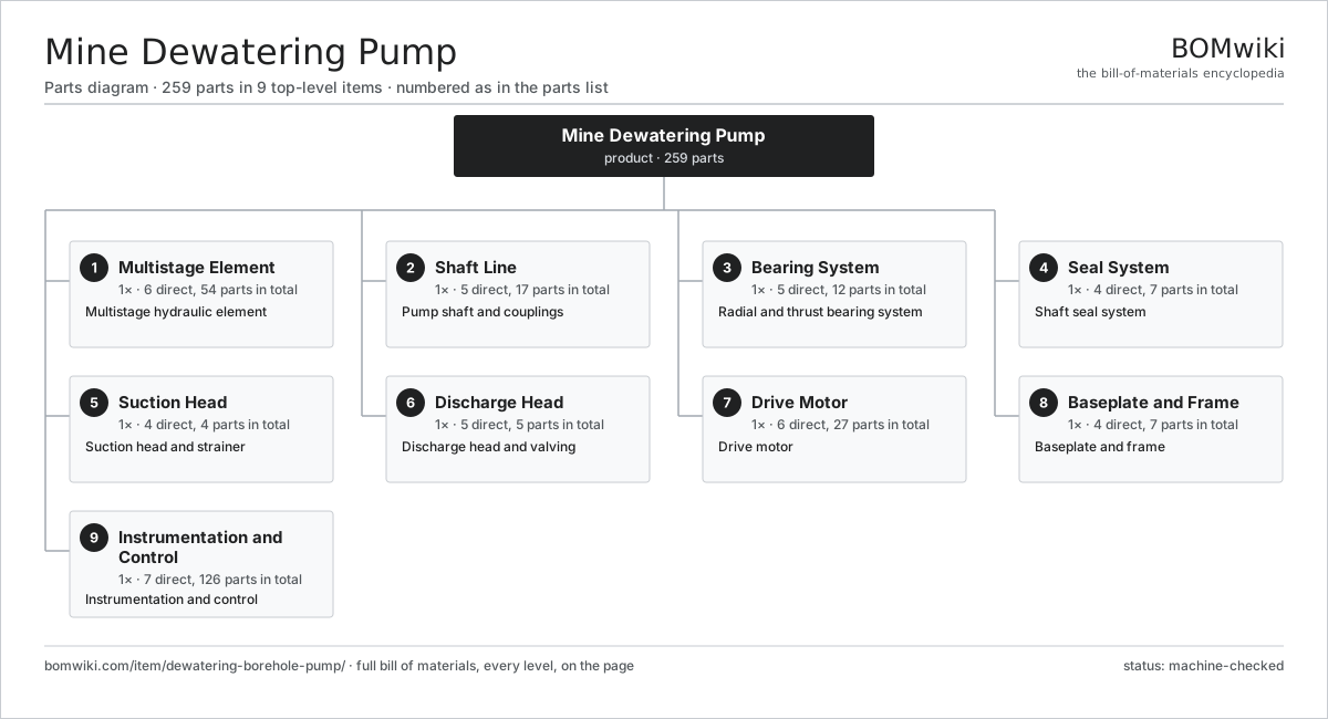
| # | Part | Qty | What it does |
|---|---|---|---|
| 1 | Multistage Element 6 parts | 1× | Multistage hydraulic element |
| 2 | Shaft Line 5 parts | 1× | Pump shaft and couplings |
| 3 | Bearing System 5 parts | 1× | Radial and thrust bearing system |
| 4 | Seal System 4 parts | 1× | Shaft seal system |
| 5 | Suction Head 4 parts | 1× | Suction head and strainer |
| 6 | Discharge Head 5 parts | 1× | Discharge head and valving |
| 7 | Drive Motor 6 parts | 1× | Drive motor |
| 8 | Baseplate and Frame 4 parts | 1× | Baseplate and frame |
| 9 | Instrumentation and Control 7 parts | 1× | Instrumentation and control |
3D model
No 3D model yet. Have a CAD file of this? Add a 3D model. STL renders right on this page; STEP, FreeCAD, and OpenSCAD sources are welcome too (openly licensed, like all 3D models on BOMwiki).
Build & assembly graph
expand / collapse · shared sub-assemblies converge · links to related products · est. labourTap an assembly to expand/collapse · tap a part to open it · use “Open page” for any node · drag to pan, scroll to zoom.
Bill of materials for Mine Dewatering Pump
9 top-level lines · 66 rows shown · 259 parts total · indented to 3 levels| # | Item / sub-assembly | Part no. | Qty/assy | Ext. qty | Parts | Type |
|---|---|---|---|---|---|---|
| 1 | Multistage Element 6 parts | dewatering-borehole-pump-stage-stack | 1× | 1 | 54 | assembly |
| 1.1 | Stage Impeller | dewatering-borehole-pump-impeller | 9× | 9 | · | part |
| 1.2 | Stage Diffuser | dewatering-borehole-pump-diffuser | 9× | 9 | · | part |
| 1.3 | Stage Casing | dewatering-borehole-pump-stage-casing | 9× | 9 | · | part |
| 1.4 | Wear Ring | dewatering-borehole-pump-wear-ring | 18× | 18 | · | part |
| 1.5 | Balance Drum | dewatering-borehole-pump-balance-drum | 1× | 1 | · | part |
| 1.6 | Tie Bolt | dewatering-borehole-pump-tie-bolt | 8× | 8 | · | part |
| 2 | Shaft Line 5 parts | dewatering-borehole-pump-shaft-line | 1× | 1 | 17 | assembly |
| 2.1 | Pump Shaft | dewatering-borehole-pump-shaft | 1× | 1 | · | part |
| 2.2 | Shaft Sleeve | dewatering-borehole-pump-shaft-sleeve | 4× | 4 | · | part |
| 2.3 | Drive Coupling | dewatering-borehole-pump-coupling | 1× | 1 | · | part |
| 2.4 | Impeller Key | dewatering-borehole-pump-impeller-key | 9× | 9 | · | part |
| 2.5 | Shaft Nut | dewatering-borehole-pump-shaft-nut | 2× | 2 | · | part |
| 3 | Bearing System 5 parts | dewatering-borehole-pump-bearing-system | 1× | 1 | 12 | assembly |
| 3.1 | Radial Bearing Housing | dewatering-borehole-pump-radial-bearing | 2× | 2 | · | part |
| 3.2 | Thrust Bearing | dewatering-borehole-pump-thrust-bearing | 1× | 1 | · | part |
| 3.3 | Ball Bearing | ball-bearing | 4× | 4 | · | part |
| 3.4 | Bearing Cooler | dewatering-borehole-pump-bearing-cooler | 1× | 1 | · | part |
| 3.5 | Oil Seal | oil-seal | 4× | 4 | · | part |
| 4 | Seal System 4 parts | dewatering-borehole-pump-seal-system | 1× | 1 | 7 | assembly |
| 4.1 | Mechanical Seal | dewatering-borehole-pump-mech-seal | 2× | 2 | · | part |
| 4.2 | Seal Flush Manifold | dewatering-borehole-pump-seal-flush | 1× | 1 | · | part |
| 4.3 | Throat Bushing | dewatering-borehole-pump-throat-bush | 2× | 2 | · | part |
| 4.4 | O-Ring Set | oring-set | 2× | 2 | · | part |
| 5 | Suction Head 4 parts | dewatering-borehole-pump-suction | 1× | 1 | 4 | assembly |
| 5.1 | Suction Casing | dewatering-borehole-pump-suction-casing | 1× | 1 | · | part |
| 5.2 | Suction Strainer | dewatering-borehole-pump-strainer | 1× | 1 | · | part |
| 5.3 | First Stage Impeller | dewatering-borehole-pump-first-stage-impeller | 1× | 1 | · | part |
| 5.4 | Fastener Set | fastener-set | 1× | 1 | · | part |
| 6 | Discharge Head 5 parts | dewatering-borehole-pump-discharge | 1× | 1 | 5 | assembly |
| 6.1 | Discharge Casing | dewatering-borehole-pump-discharge-casing | 1× | 1 | · | part |
| 6.2 | Check Valve | dewatering-borehole-pump-check-valve | 1× | 1 | · | part |
| 6.3 | Isolation Valve | dewatering-borehole-pump-isolation-valve | 1× | 1 | · | part |
| 6.4 | Pressure Sensor | pressure-sensor | 1× | 1 | · | part |
| 6.5 | Fastener Set | fastener-set | 1× | 1 | · | part |
| 7 | Drive Motor 6 parts | dewatering-borehole-pump-motor | 1× | 1 | 27 | assembly |
| 7.1 | Stator Assembly 3 parts | stator-assembly | 1× | 1 | 3 | assembly |
| 7.1.1 | Stator Core (laminations) | stator-core | 1× | 1 | · | part |
| 7.1.2 | Copper Winding | copper-winding | 1× | 1 | · | part |
| 7.1.3 | Slot Insulation | stator-insulation | 1× | 1 | · | part |
| 7.2 | Rotor Assembly 4 parts | rotor-assembly | 1× | 1 | 19 | assembly |
| 7.2.1 | Rotor Shaft | rotor-shaft | 1× | 1 | · | part |
| 7.2.2 | Rotor Core | rotor-core | 1× | 1 | · | part |
| 7.2.3 | Neodymium Magnet | neodymium-magnet | 16× | 16 | · | part |
| 7.2.4 | Ball Bearing | ball-bearing | 1× | 1 | · | part |
| 7.3 | Ball Bearing | ball-bearing | 2× | 2 | · | part |
| 7.4 | Motor Housing | dewatering-borehole-pump-motor-housing | 1× | 1 | · | part |
| 7.5 | Motor Cooling Fan | dewatering-borehole-pump-motor-fan | 1× | 1 | · | part |
| 7.6 | Terminal Box | dewatering-borehole-pump-terminal-box | 1× | 1 | · | part |
| 8 | Baseplate and Frame 4 parts | dewatering-borehole-pump-baseplate | 1× | 1 | 7 | assembly |
| 8.1 | Baseplate | dewatering-borehole-pump-base | 1× | 1 | · | part |
| 8.2 | Vibration Isolator | dewatering-borehole-pump-isolator | 4× | 4 | · | part |
| 8.3 | Coupling Guard | dewatering-borehole-pump-coupling-guard | 1× | 1 | · | part |
| 8.4 | Fastener Set | fastener-set | 1× | 1 | · | part |
| 9 | Instrumentation and Control 7 parts | dewatering-borehole-pump-instrumentation | 1× | 1 | 126 | assembly |
| 9.1 | Pump Controller 4 parts | dewatering-borehole-pump-controller | 1× | 1 | 100 | assembly |
| 9.1.1 | Bare PCB | pcb-bare | 1× | 1 | · | part |
| 9.1.2 | Microcontroller | mcu | 1× | 1 | · | part |
| 9.1.3 | SMD Passive (R/C/L) | smd-passives | 90× | 90 | · | part |
| 9.1.4 | Connector | connector | 8× | 8 | · | part |
| 9.2 | Vibration Sensor | dewatering-borehole-pump-vibration-sensor | 2× | 2 | · | part |
| 9.3 | Temperature Sensor | dewatering-borehole-pump-temp-sensor | 4× | 4 | · | part |
| 9.4 | Flow Meter | dewatering-borehole-pump-flow-meter | 1× | 1 | · | part |
| 9.5 | Level Probe | dewatering-borehole-pump-level-probe | 2× | 2 | · | part |
| 9.6 | Wire Bundle | wire-bundle | 1× | 1 | · | part |
| 9.7 | Connector | connector | 16× | 16 | · | part |
Related products
same domain, ranked by shared parts Irrigation Pump Station
1,881 parts · shares 7 with this page
Irrigation Pump Station
1,881 parts · shares 7 with this page
 Sluice Gate
123 parts · shares 5 with this page
Sluice Gate
123 parts · shares 5 with this page
 Centrifugal Compressor
338 parts · shares 5 with this page
Centrifugal Compressor
338 parts · shares 5 with this page
 Radial Spillway Gate
264 parts · shares 5 with this page
Radial Spillway Gate
264 parts · shares 5 with this page
 Control Valve
46 parts · shares 5 with this page
Hydraulic Test Bench
77 parts · shares 5 with this page
Control Valve
46 parts · shares 5 with this page
Hydraulic Test Bench
77 parts · shares 5 with this page
Sourcing: possible vendors
Browse the supplier directory → Prices, MOQ, and lead times are algorithmic estimates, not quotes, and not claims about these companies. Company mappings are curated by keyword; est. price band $50–$50k. How estimates work| Vendor | HQ | Specialty | MOQ | Lead time |
|---|---|---|---|---|
|
🇩🇰Grundfos
grundfos.com ↗
|
Bjerringbro, DK | Pumps | 200 units | 6–12 wks |
|
🇺🇸Xylem
xylem.com ↗
|
Washington, US | Water technology | 200 units | 6–12 wks |
| flowserve.com ↗ | Irving, US | Pumps & valves | 200 units | 6–12 wks |
|
🇩🇪KSB
ksb.com ↗
|
Frankenthal, DE | Pumps & valves | 200 units | 6–12 wks |
| parker.com ↗ | Cleveland, US | Motion & fluid control | 200 units | 6–12 wks |
986-word article